Article support system

a support system and article technology, applied in the direction of suction cups, machine supports, domestic objects, etc., can solve the problems of limited to a particular support arrangement, and each of these arrangements has its limitations

Inactive Publication Date: 2005-07-05
RICHTER HARALD
View PDF12 Cites 71 Cited by
  • Summary
  • Abstract
  • Description
  • Claims
  • Application Information

AI Technical Summary

Problems solved by technology

They have generally however the disadvantage that they are limited to a par

Method used


Image

  • Article support system
  • Article support system
  • Article support system

Examples


Embodiment Construction

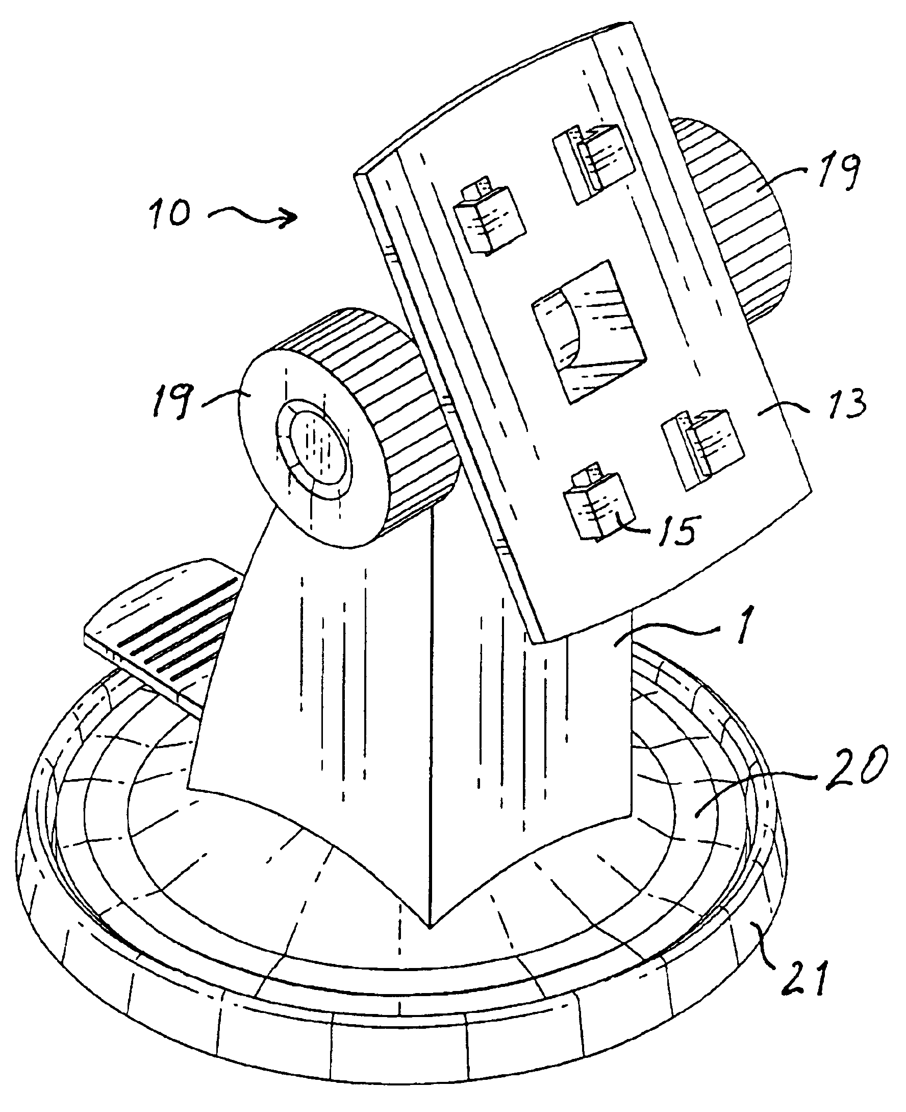
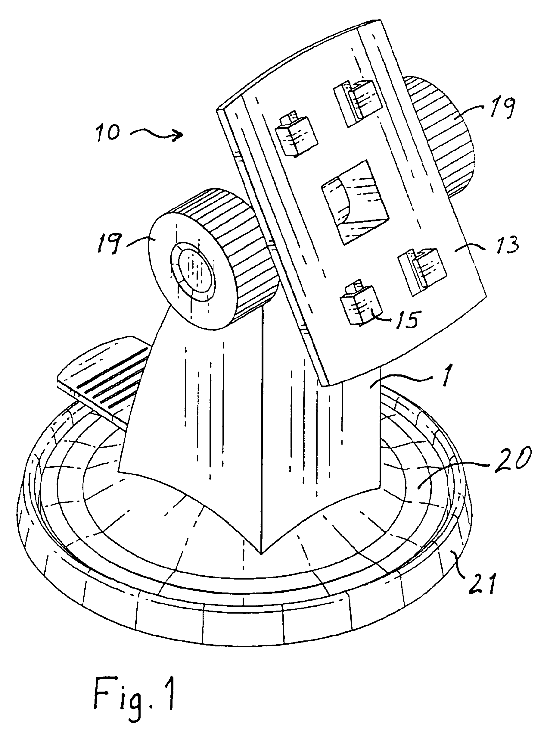
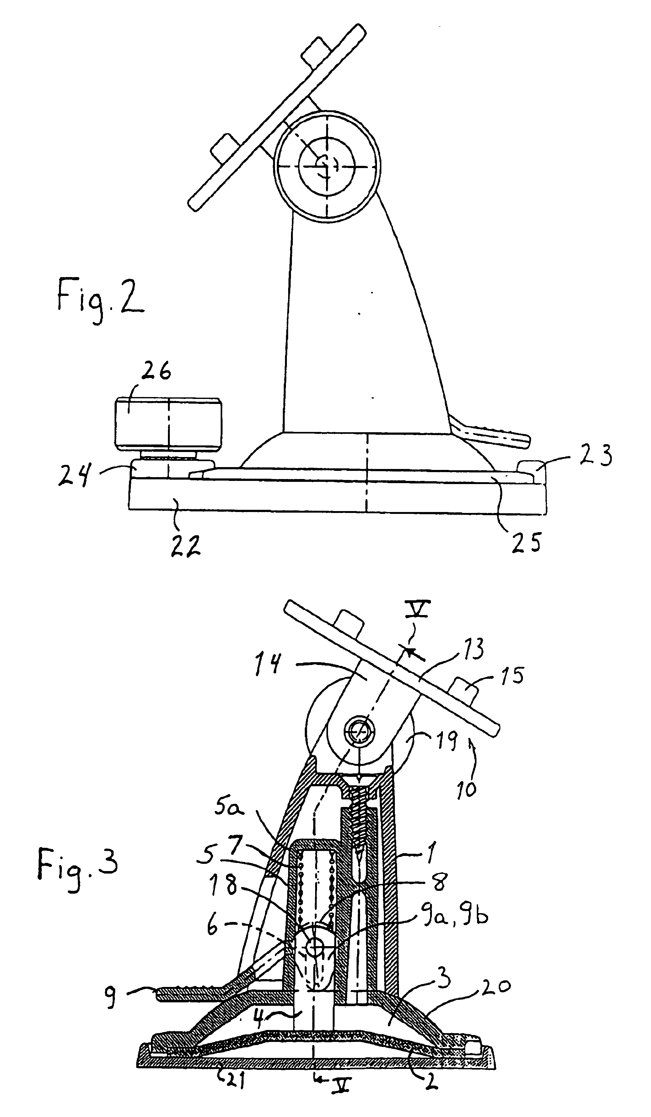
[0017]The article support system according to the invention comprises an article support column 1 with a base 20 and a support structure 10 which is pivotally supported in the column 1. The column 1 includes an operating mechanism for operating a suction disc 2 (FIG. 3) disposed in the base 20. The base 20 includes a cavity 3 across which the suction disc 2 extends. The housing 1 also includes a sleeve 5 receiving a rod 4, which is connected to the disc 2 for operating the disc 2. A shaft 18 extends transversely through the rod 4 and through axial slots 6 forked in the sleeve 5 and also through actuating arms 9a and 9b of a U-shaped actuating member 9. The actuating arms 9a and 9b are provided with cams 9c, which engage the base 20 at opposites sides of the sleeve 5 so that, upon pivoting the U-shaped actuating member 9 toward the base 20, the shaft 18 and, together therewith, the rod 4 are moved upwardly in the sleeve 5 thereby pulling the suction disc 2 into the housing 1 as the c...


PUM


Abstract

In an article support system including a housing with a base defining a cavity, a suction disc supported in the cavity so as to delimit the cavity, and a mechanism for actuating the suction disc so as to create a vacuum between the suction disc and a smooth support surface, the housing includes at its end opposite the base an article support plate with engagement claws for engaging a particular article, and a mounting plate is provided for connection to a support surface, which has a smooth surface for mounting the device selectively thereon by way of the suction disc or on a clamp support plate.

Description

BACKGROUND OF THE INVENTION[0001]The invention relates to an article support system, that is, a system for supporting an article on various surfaces and in various ways, particularly in a motor vehicle.[0002]Devices for supporting articles such as cellular phones, for example on the dashboard or by suction cups on a window are known. They have generally however the disadvantage that they are limited to a particular support arrangement. The support arrangement may include a suction cup holder, it may include a screw-down structure or a hook-and-loop (velcro) structure. The support device may also be cemented to the support surface.[0003]Each of these arrangements has its limitations. There are advantages and disadvantages to each of the support arrangements but one particular arrangement must be chosen by the user.[0004]It is therefore the object of the present invention to provide an article support system with an article holder, which can be mounted to a support base and which can ...

Claims


Application Information

Patent Timeline
IPC IPC(8): F16C11/10F16B47/00F16C11/04F16M13/02F16M11/04F16M11/02F16M11/10B60R11/00
CPCF16B47/006F16C11/10F16M11/04F16M11/041F16M11/10F16M13/00F16M13/02F16M13/022B60R2011/0056F16M2200/02
Inventor RICHTER, HERBERT
Owner RICHTER HARALD
Why Eureka
Try Eureka