Head-protection airbag device

a technology for airbags and head protection, which is applied in the direction of pedestrian/occupant safety arrangements, vehicular safety arrangments, vehicle components, etc., can solve the problem of not being able to deploy each portion of the airbag, and achieve the effect of reducing the time for completion and completing the deploymen

Inactive Publication Date: 2005-07-05
TOYOTA JIDOSHA KK
View PDF53 Cites 20 Cited by
  • Summary
  • Abstract
  • Description
  • Claims
  • Application Information

AI Technical Summary

Benefits of technology

[0014]In the head-protection airbag device according to the second and third aspects of the invention, upon side impact, rollover or the like of the vehicle, the gas is supplied from the gas supplier into the inflation chambers of the airbag, whereby the airbag is inflated and deployed like a curtain along the sidewall of the vehicle compartment. At this point, only the predetermined inflation chambers of the airbag can receive the gas from an early stage. Accordingly, the predetermined inflation chambers can be inflated and deployed quickly. This enables deployment of the airbag (curtain-like deployment) to be completed before a sufficient amount of gas flows into every inflation chamber of the airbag, allowing a reduction in the time for completion of deployment of the airbag.
[0015]In each of the aforementioned aspects of the invention, the predetermined inflation chambers may have a smaller volume than that of the remainder. Thus, the predetermined inflation chambers can be inflated and deployed with a smaller amount of gas, allowing a further reduction in the time for completion of deployment of the airbag.
[0016]In each of the aforementioned aspects of the invention, the predetermined inflation chambers may be disposed at locations away from the head of the seated occupant in a fore-and-aft direction of the vehicle. Accordingly, the airbag can be deployed with an inflation chamber at a location corresponding to the head of the seated occupant being insufficiently inflated. This enables the airbag to be accurately interposed between the sidewall of the vehicle compartment and the head of the seated occupant even if there is only a small space therebetween.

Problems solved by technology

It is therefore impossible to deploy each portion of the airbag (e.g., the portions respectively corresponding to a door glass portion and a pillar garnish portion) in an optimal direction.

Method used


Image

  • Head-protection airbag device
  • Head-protection airbag device
  • Head-protection airbag device

Examples


first embodiment

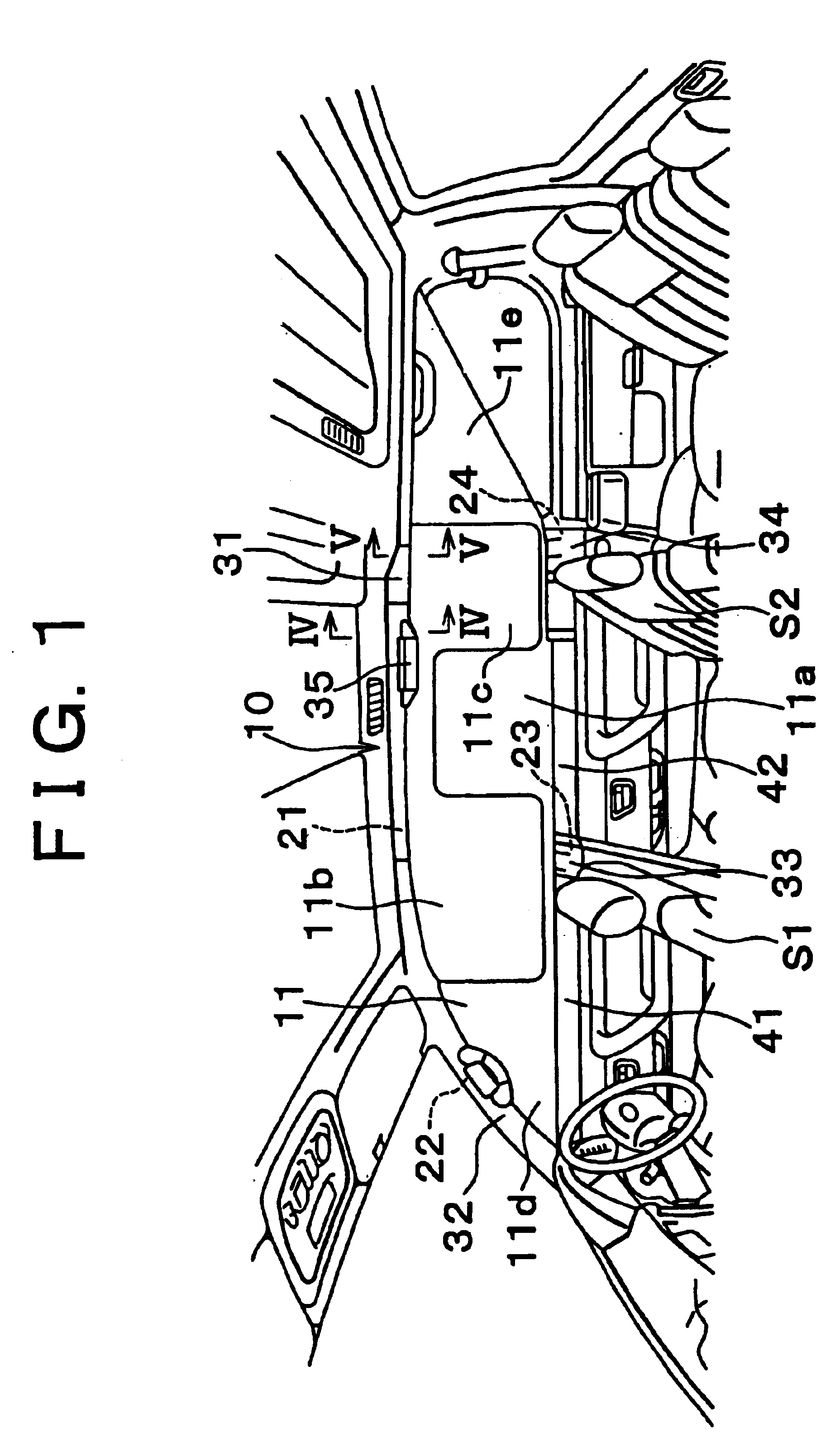
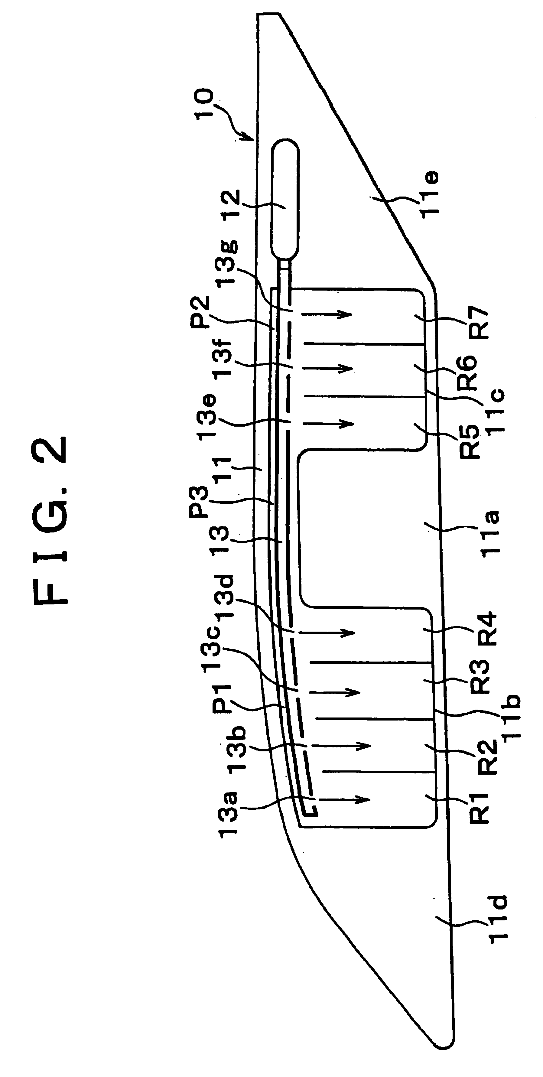
[0028]Hereinafter, the invention will be described in conjunction with the drawings. A head-protection airbag device 10 of the invention shown FIGS. 1 and 2 includes an airbag 11 inflated and deployed like a curtain along the sidewall of the vehicle compartment so as to protect the head of the occupant seated in a front seat S1 (the seat corresponding to a B pillar 23) and the head of the occupant seated in a rear front seat S2 (the seat corresponding to a C pillar 24), an inflator 12 serving as a gas supplier for supplying a gas to the airbag 11, and a gas distribution pipe 13 for distributing the gas supplied from the inflator 12 to each inflation chamber R1 to R7 of the airbag 11.

[0029]The airbag 11 is formed from foundation cloth (woven fabric) having an airtight coating thereon (the airtight coating may be omitted). As shown in FIGS. 1 and 2, the airbag 11 has a front-seat inflatable portion 11b and a rear-seat inflatable portion 11c with a central non-inflatable portion 11a in...

third embodiment

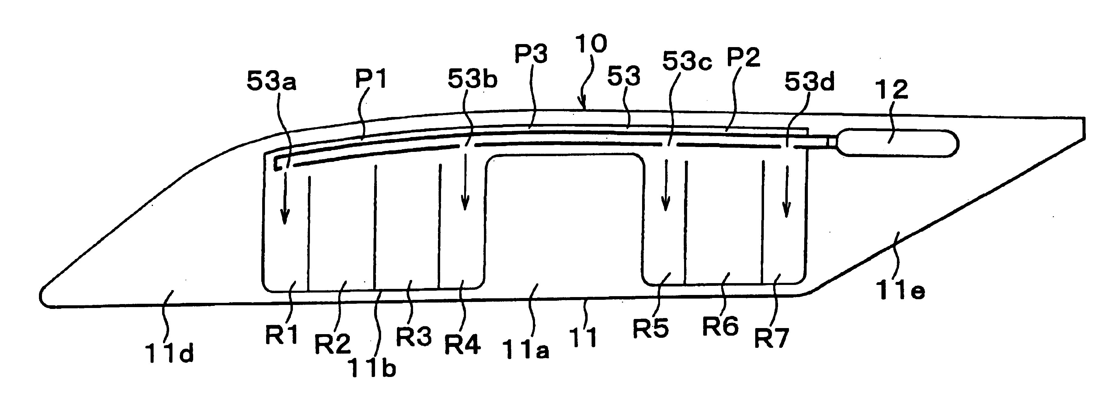
[0044]In the invention, a gas distribution pipe 53 is closed at its front end and is hermetically connected to the inflator 12 at its rear end. The gas distribution pipe 53 extends through the gas-introducing paths P1, P2 and P3 via the opening at the rear end of the rear gas-introducing path P2, and is hermetically sealed at this opening. The gas distribution pipe 53 includes gas outlets 53a, 53b corresponding to the front-seat inflatable portion 11b of the airbag 11, and gas outlets 53c, 53d corresponding to the rear-seat inflatable portion 11c.

[0045]The gas outlets 53a and 53b respectively correspond to the inflation chambers R1 and R4 which are disposed at the locations away from the head of the occupant in the front seat in the fore-and-aft direction of the vehicle. The gas outlets 53a and 53b are respectively opened toward the bottom of the inflation chambers R1 and R4, so that they can supply a gas to the respective inflation chambers R1 and R4. Note that part of the gas sup...

sixth embodiment

[0054]In each of the above embodiments, the inflator 12 may supply a gas to each inflation chamber R1 to R7 of the airbag 11 through the gas distribution pipe 53 extending through the gas-introducing paths P1 to P3 of the airbag 11. As in the invention shown in FIG. 10, however, the gas distribution pipe 53 may be eliminated so that the inflator 12 supplies a gas to each inflation chamber R1 to R7 of the airbag 11 through the gas-introducing paths P1 to P3 of the airbag 11.

[0055]Note that, in the sixth embodiment of FIG. 10, the inflation chambers R1 and R4 communicate with the gas-introducing path P1, and the inflation chambers R5 and R7 communicate with the gas-introducing path P2. Moreover, the inflation chambers R1 to R4 and the inflation chambers R5 to R7 each communicate with each other at their respective lower ends. In the sixth embodiment of FIG. 10, the inflator 12 is hermetically attached to the rear end of the rear gas-introducing path P2 in the airbag 11.

[0056]In the th...


PUM


Abstract

The head-protection airbag device comprises an airbag stored along a roof side rail and including a gas-introducing path at its upper edge. A gas is supplied from a gas supplier into an inflation chamber through a gas distribution pipe provided within the gas-introducing path, whereby the airbag is inflated and deployed like a curtain along a sidewall of a vehicle compartment so as to protect a head of an occupant. Gas outlets of the gas distribution pipe are oriented in different directions in a region corresponding to a door glass portion and in a region corresponding to a pillar garnish portion.

Description

INCORPORATION BY REFERENCE[0001]This is a Divisional of application Ser. No. 09 / 935,597 filed on Aug. 24, 2001, now U.S. Pat. No. 6,705,640. The entire disclosure of the prior application, including the specification, drawings, and abstract are incorporated herein by reference in its entirety.BACKGROUND OF THE INVENTION[0002]1. Field of the Invention[0003]The invention relates to a head-protection airbag device mounted in vehicles.[0004]2. Description of Related Art[0005]This type of head-protection airbag devices includes a head-protection airbag device in which an airbag stored along a roof side rail has a gas-introducing path at its upper edge. A gas is supplied from a gas supplier into an inflation chamber through a gas distribution pipe provided within the gas-introducing path, whereby the airbag is inflated and deployed like a curtain along the sidewall of the vehicle compartment so as to protect a head of an occupant. Such a head-protection airbag device is described in, e.g....

Claims


Application Information

Patent Timeline
Patent Type & Authority Patents(United States)
IPC IPC(8): B60R21/16B60R21/26B60R21/213B60R21/232B60R21/233B60R21/262
CPCB60R21/232B60R2021/23316B60R2021/2617
Inventor TAKAHASHI, HIROYUKI
Owner TOYOTA JIDOSHA KK
Why Eureka
Try Eureka