Counter-top cooker having multiple heating elements

a technology of counter-top cookers and heating elements, which is applied in the field of counter-top cookers, can solve problems such as cooking tim

Inactive Publication Date: 2005-07-12
NUWAVE
View PDF16 Cites 98 Cited by
  • Summary
  • Abstract
  • Description
  • Claims
  • Application Information

AI Technical Summary

Problems solved by technology

Also, while the known counter-top cookers do cook faster than conventional ovens, the cooking time is still considered by some to be long enough that it does not act as an incentive to purchase the counter-top cookers.

Method used


Image

  • Counter-top cooker having multiple heating elements
  • Counter-top cooker having multiple heating elements
  • Counter-top cooker having multiple heating elements

Examples


Embodiment Construction

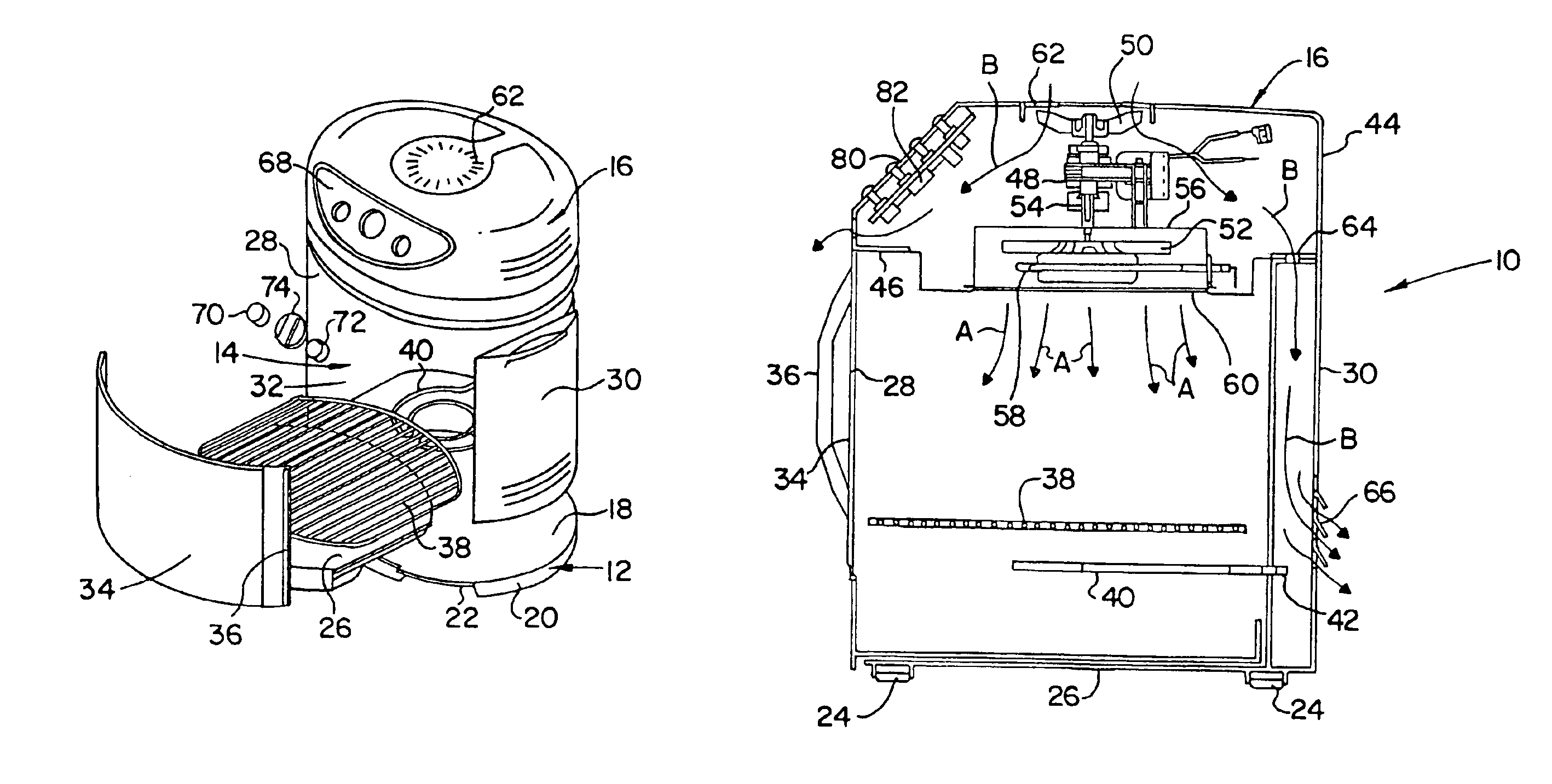
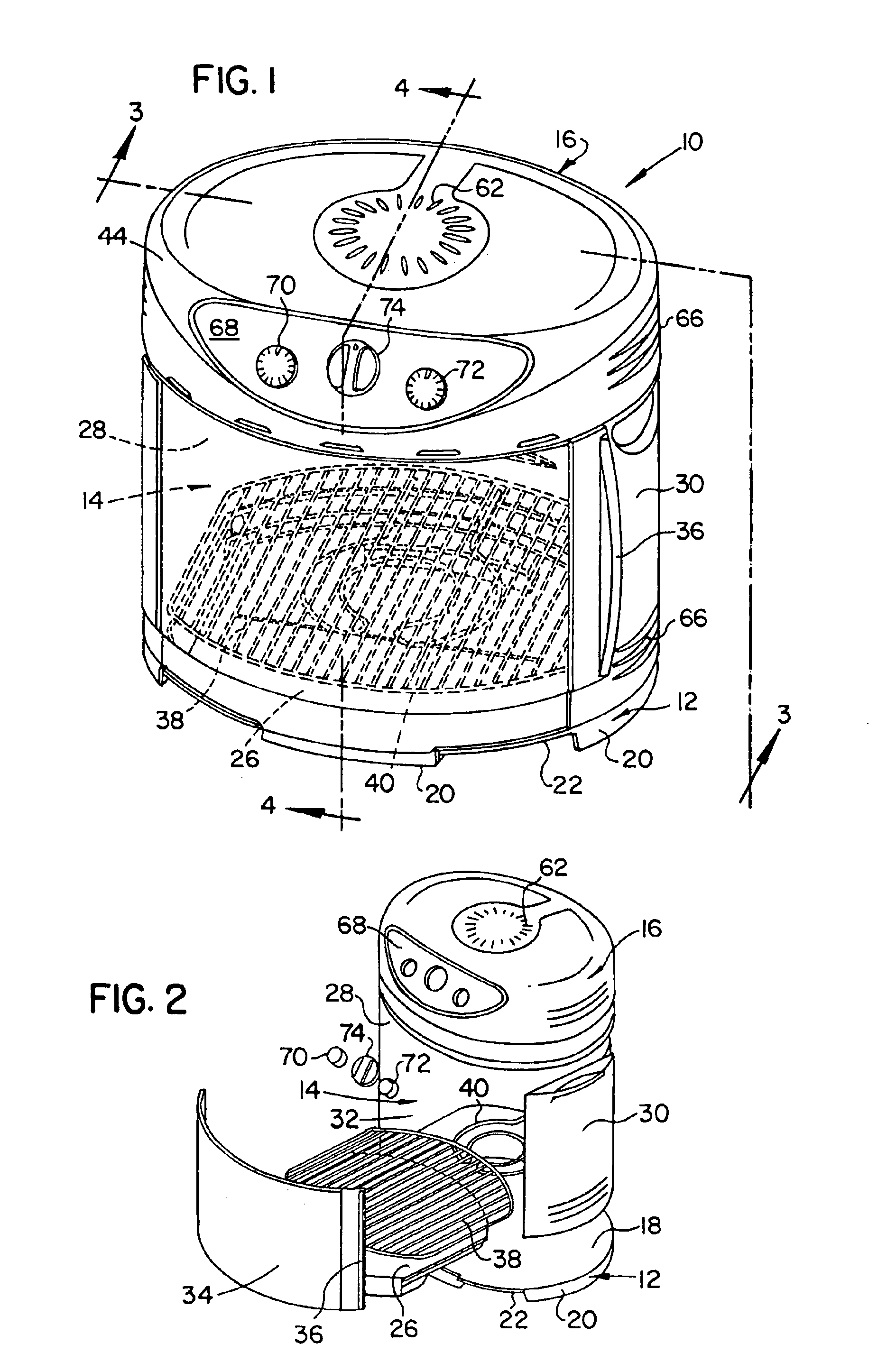
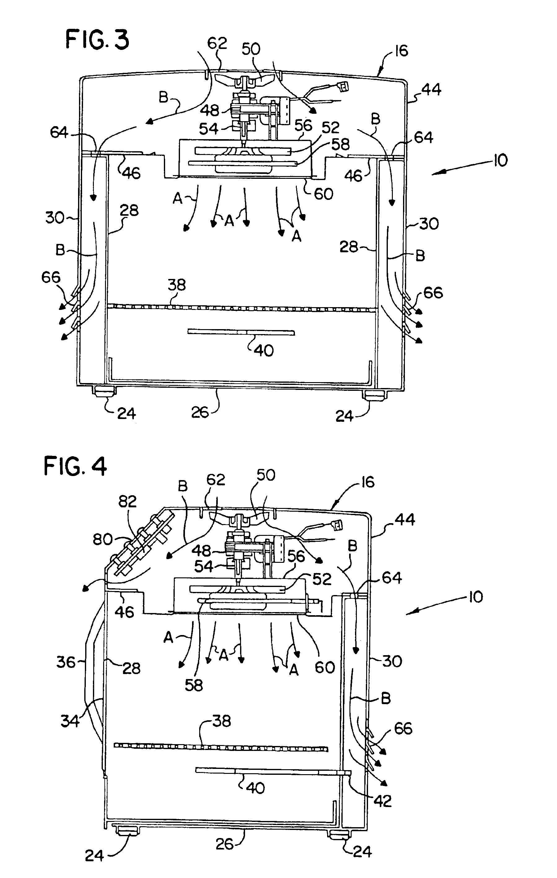
[0012]Turning to FIGS. 1 and 2, the counter-top cooker or oven in accordance with one embodiment of the present invention is indicated generally at 10, and includes a base 12, a cooking chamber 14 and a power head 16. The base 12 includes a generally planar top surface 18 and a plurality of supports 20 on the opposite side of the top surface. The supports 20 are adapted to rest on a surface, a countertop, for example, and insulate the surface from the heat generated in the cooking chamber 14. Rubber feet 24 (best shown in FIGS. 3 and 4) may be attached to the supports 20 to prevent the oven 10 from sliding.

[0013]The cooking chamber is 14 is defined by a generally oval-shaped drip pan 26 that removably slides into the cooking chamber 14 and onto the top of the base 12, and a vertical inner wall 28 which surrounds the bottom of the cooking chamber and extends upwardly from the base. In the preferred embodiment, the drip pan 26 is made of aluminum, and the inner wall 28 is made of alum...


PUM


Abstract

A counter-top cooker includes a base, a cooking chamber having a top end and a bottom end supported on the base, and a power head attached to the top end of the cooking chamber. The power head includes a heating element and a fan for directing airflow over the heating element and into the cooking chamber. The cooker also includes another heating element provided in the cooking chamber proximate the bottom end of the cooking chamber.

Description

FIELD OF THE INVENTION[0001]This invention relates to counter-top cookers, and in particular to a counter-top electric cooker having a radiant heating element in addition to the convection heating element in a power head.BACKGROUND OF THE INVENTION[0002]Counter-top electric cookers or ovens are known in the art. In comparison to conventional ovens, counter-top cookers offer the advantage of being less bulky and having quicker cooking times. Typically, the counter-top cookers include a power head having an electric heating unit that generates heat in the cooking enclosure. To reduce the cooking time, counter-top cookers typically will rely on a hot air stream that is produced by a high speed fan provided in the power head upstream of an electric heating element, or by utilizing an infrared heating element in combination with a relatively low speed fan that generates sufficient air circulation in the oven to cook the food.[0003]In types of cooking such as roasting or broiling, it is d...

Claims


Application Information

Patent Timeline
Patent Type & Authority Patents(United States)
IPC IPC(8): A47J39/00F24C15/32F24C15/00F24C7/10
CPCA47J37/0623A47J37/0641F24C7/10F24C15/006F24C15/325F24C7/046
Inventor MOON, JUNG S.LIU, RONGCHAE, KITAKKIM, JONGROK
Owner NUWAVE
Why Eureka
Try Eureka