
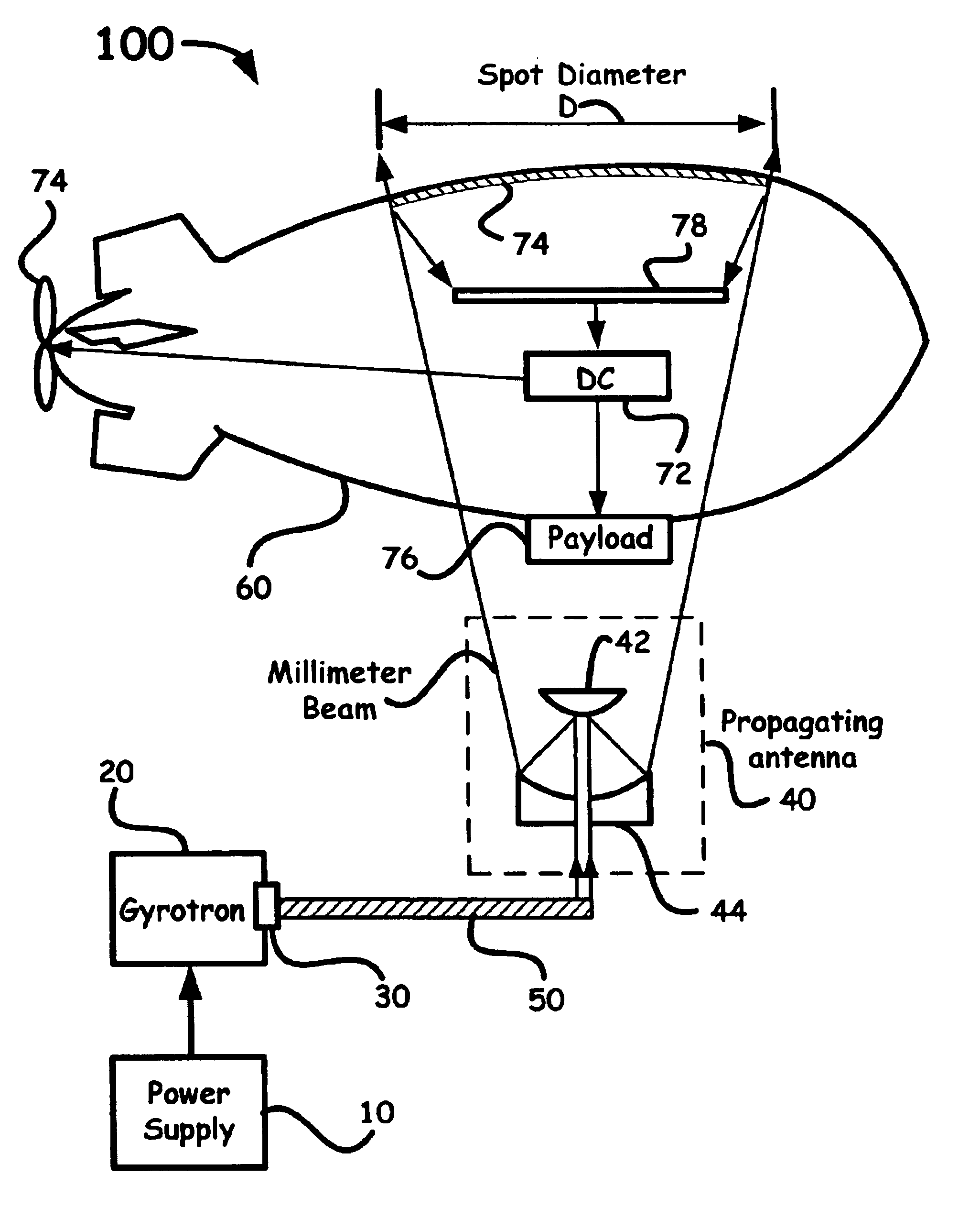
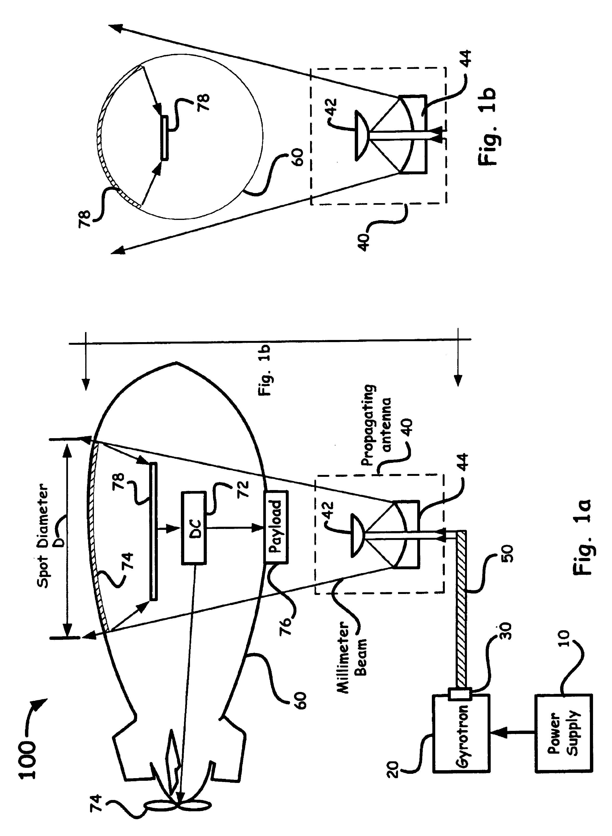
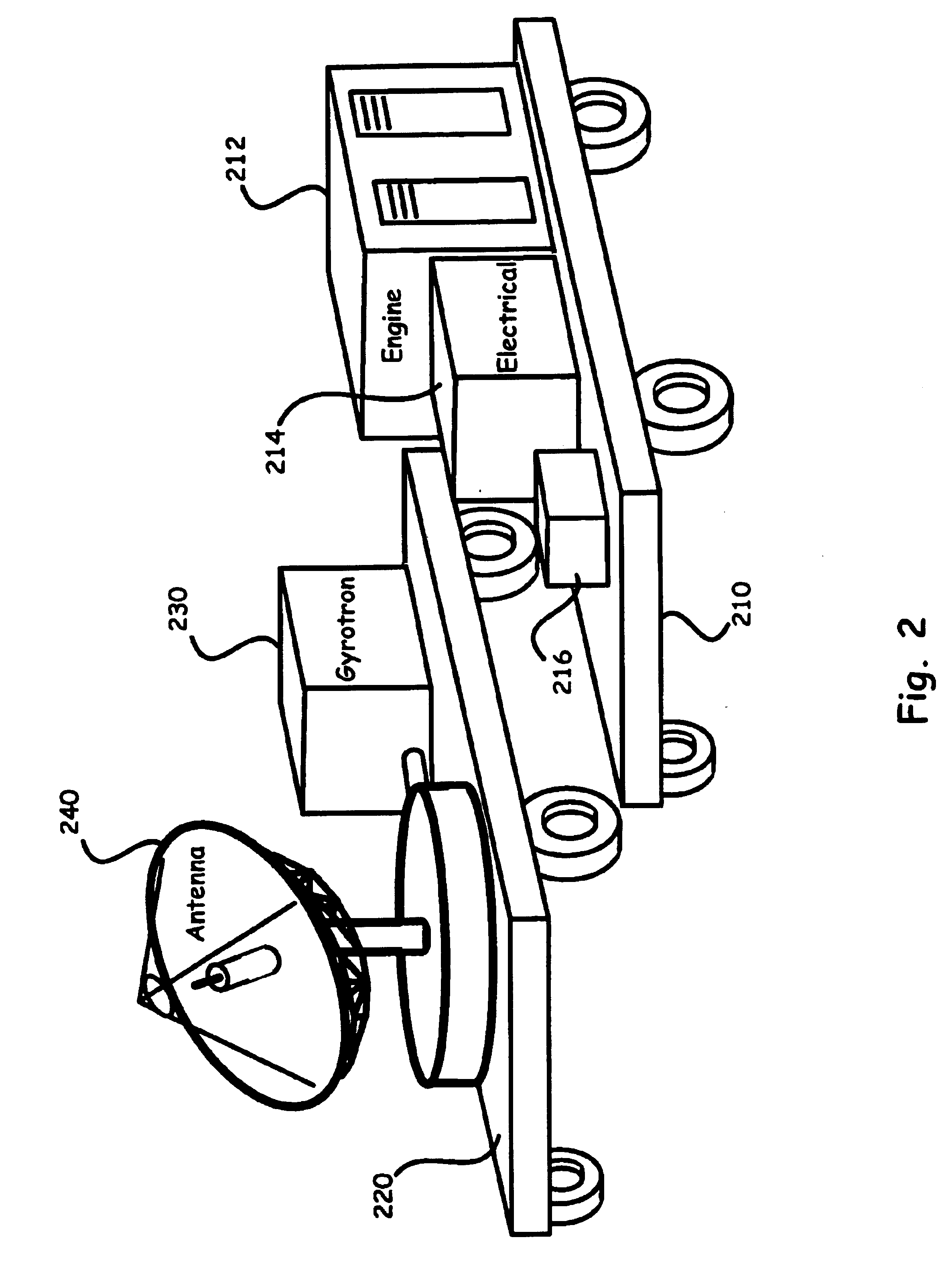
System using a megawatt class millimeter wave source and a high-power rectenna to beam power to a suspended platform

a millimeter wave source and high-power rectenna technology, applied in the field of power beaming, can solve the problems of reduced atmospheric density, difficult flight of non-orbiting platforms, and known parts, and achieve the effect of using power

Inactive Publication Date: 2005-07-19
LAWRENCE LIVERMORE NAT SECURITY LLC
View PDF6 Cites 49 Cited by
  • Summary
  • Abstract
  • Description
  • Claims
  • Application Information

AI Technical Summary

Problems solved by technology

Power beaming energy from a first location (e.g., on Earth, a high altitude suspended platform or a satellite) to a remote location (e.g., on Earth, a high altitude suspended platform or a satellite) has provided particular problems known only to those skilled in the art.
At higher altitude, the reduction in atmospheric density makes flight difficult for these non-orbiting platforms.
Platforms that carry their own fuel, both lighter than aircraft (balloons or airships) and conventional aircraft, cannot stay aloft for time periods (e.g., months to years) that are presently envisioned.
Platforms that rely on solar power suffer from the weight of the large area solar cells and the requirement of energy storage for nighttime operation and higher than average peak propulsion loads.
However, such a scheme, while attractive in concept, provides for an efficiency of only about 50% and the weight is high, thereby lowering an allowed payload.
However, the size of the transmitting arrays is too large for mobile and tactical applications.
Conversion of such beam powered electromagnetic radiation into useful electrical power by a receiving antenna (i.e., a rectenna or rectifying antenna) has also been utilized in the past but has not received significant recent development.
While there have been attempts to fabricate a large area rectenna using such a configuration that includes a single Shottky diode as a rectifying element, several factors, such as low reverse breakdown voltages at the junction, low current densities during forward biasing, and high junction capacitances have combined to limit power densities on the rectenna, thus requiring large areas to convert the received millimeter wave energy to DC power.
Moreover, the large rectenna panels add to the weight and cost of such a receiving system.

Method used


Image

  • System using a megawatt class millimeter wave source and a high-power rectenna to beam power to a suspended platform
  • System using a megawatt class millimeter wave source and a high-power rectenna to beam power to a suspended platform
  • System using a megawatt class millimeter wave source and a high-power rectenna to beam power to a suspended platform

Examples


Embodiment Construction

[0023]Referring now to the following detailed information, and to incorporated materials; a detailed description of the invention, including specific embodiments, is presented.

[0024]Unless otherwise indicated, numbers expressing quantities of ingredients, constituents, reaction conditions and so forth used in the specification and claims are to be understood as being modified by the term “about.” Accordingly, unless indicated to the contrary, the numerical parameters set forth in the specification and attached claims are approximations that may vary depending upon the desired properties sought to be obtained by the subject matter presented herein. At the very least, and not as an attempt to limit the application of the doctrine of equivalents to the scope of the claims, each numerical parameter should at least be construed in light of the number of reported significant digits and by applying ordinary rounding techniques. Notwithstanding that the numerical ranges and parameters setti...


PUM


Abstract

A system for beaming power to a high altitude platform is based upon a high power millimeter gyrotron source, optical transmission components, and a high-power receiving antenna (i.e., a rectenna) capable of rectifying received millimeter energy and converting such energy into useable electrical power.

Description

RELATED APPLICATION[0001]This application claims the benefit of U.S. Provisional Application No. 60 / 442,331, filed Jan. 23, 2003, and U.S. Provisional Application No. 60 / 482,625, filed Jun. 25, 2003, both entitled, “A System Using a Megawatt Class Millimeter Wave Source and a Field Emitting Diode-Rectenna to Beam Power to a Suspended Platform,” which are incorporated herein by this reference.[0002]The United States Government has rights in this invention pursuant to Contract No. W-7405-ENG-48 between the United States Department of Energy and the University of California for the operation of Lawrence Livermore National Laboratory.BACKGROUND OF THE INVENTION[0003]1. Field of the Invention[0004]The present invention relates in general to the art of power beaming and more particularly to a millimeter wave power beaming system.[0005]2. Description of Related Art[0006]Power beaming energy from a first location (e.g., on Earth, a high altitude suspended platform or a satellite) to a remot...

Claims


Application Information

Patent Timeline
Patent Type & Authority Patents(United States)
IPC IPC(8): H01S3/30H01Q1/28H01Q1/27H01Q1/24H01Q19/13H02J17/00
CPCH01Q1/248H01Q1/28H01Q19/13H02J17/00H02J50/27H02J50/90
Inventor CAPLAN, MALCOLMFRIEDMAN, HERBERT W.
Owner LAWRENCE LIVERMORE NAT SECURITY LLC
Learn More