Coax core insulator waveguide

a core insulator and waveguide technology, applied in waveguides, basic electric elements, electrical appliances, etc., can solve the problems of limiting length and emission, optical solutions that are not cost effective, and free air wireless solutions

Inactive Publication Date: 2011-03-29
SONY CORP +1
View PDF3 Cites 431 Cited by
  • Summary
  • Abstract
  • Description
  • Claims
  • Application Information

AI Technical Summary

Problems solved by technology

This has been done with multiple wires in parallel but length and emissions are a limiting factor.
Optical solutions

Method used


Image

  • Coax core insulator waveguide
  • Coax core insulator waveguide
  • Coax core insulator waveguide

Examples


Embodiment Construction

While this invention is susceptible of embodiment in many different forms, there is shown in the drawings and will herein be described in detail specific embodiments, with the understanding that the present disclosure of such embodiments is to be considered as an example of the principles and not intended to limit the invention to the specific embodiments shown and described. In the description below, like reference numerals are used to describe the same, similar or corresponding parts in the several views of the drawings.

The terms “a” or “an”, as used herein, are defined as one or more than one. The term “plurality”, as used herein, is defined as two or more than two. The term “another”, as used herein, is defined as at least a second or more. The terms “including” and / or “having”, as used herein, are defined as comprising (i.e., open language). The term “coupled”, as used herein, is defined as connected, although not necessarily directly, and not necessarily mechanically.

Reference...


PUM


Abstract

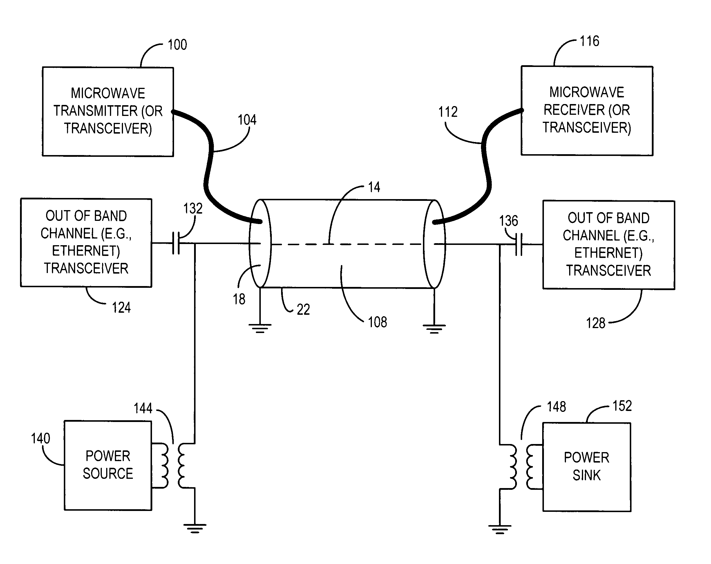
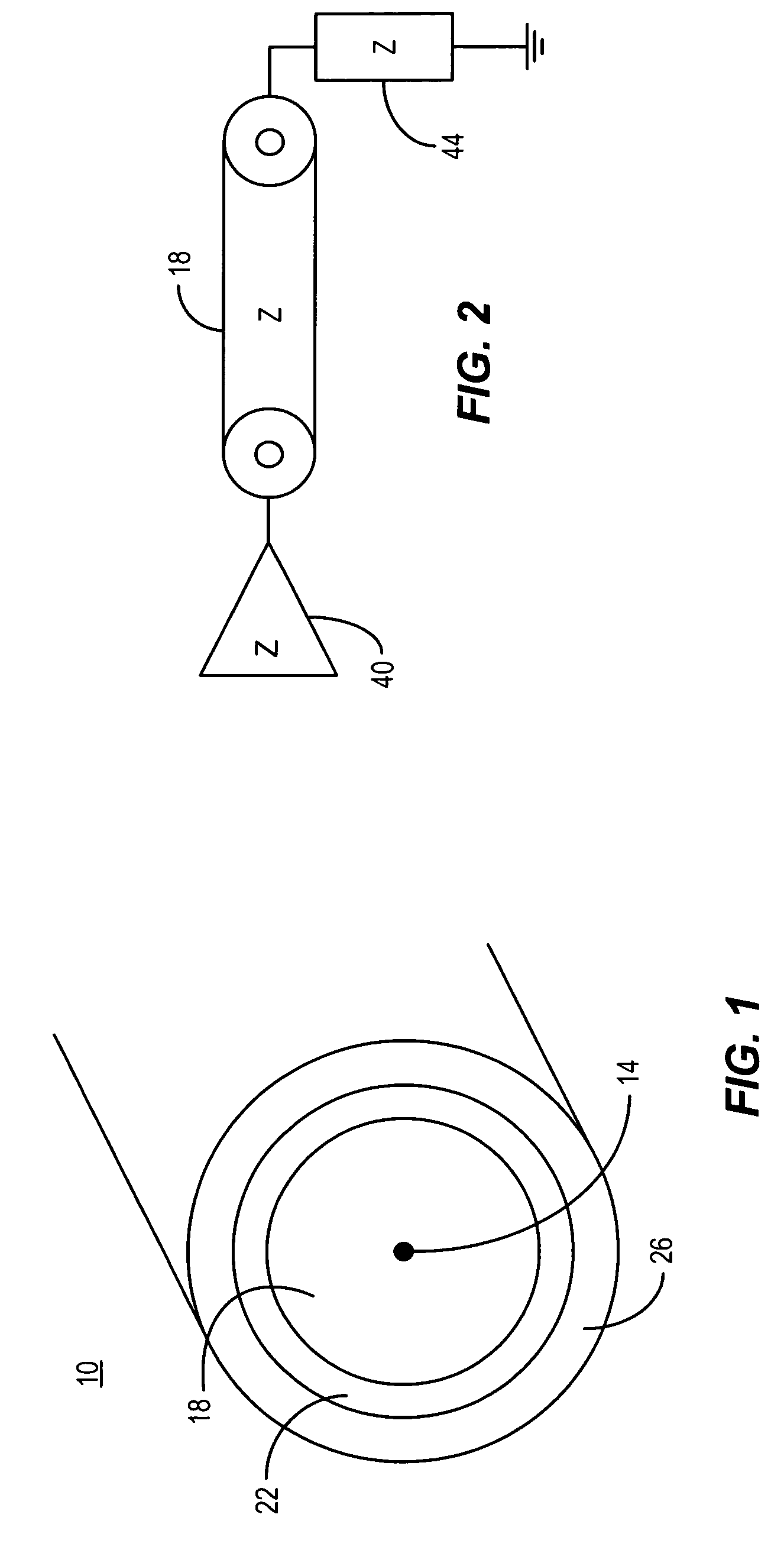
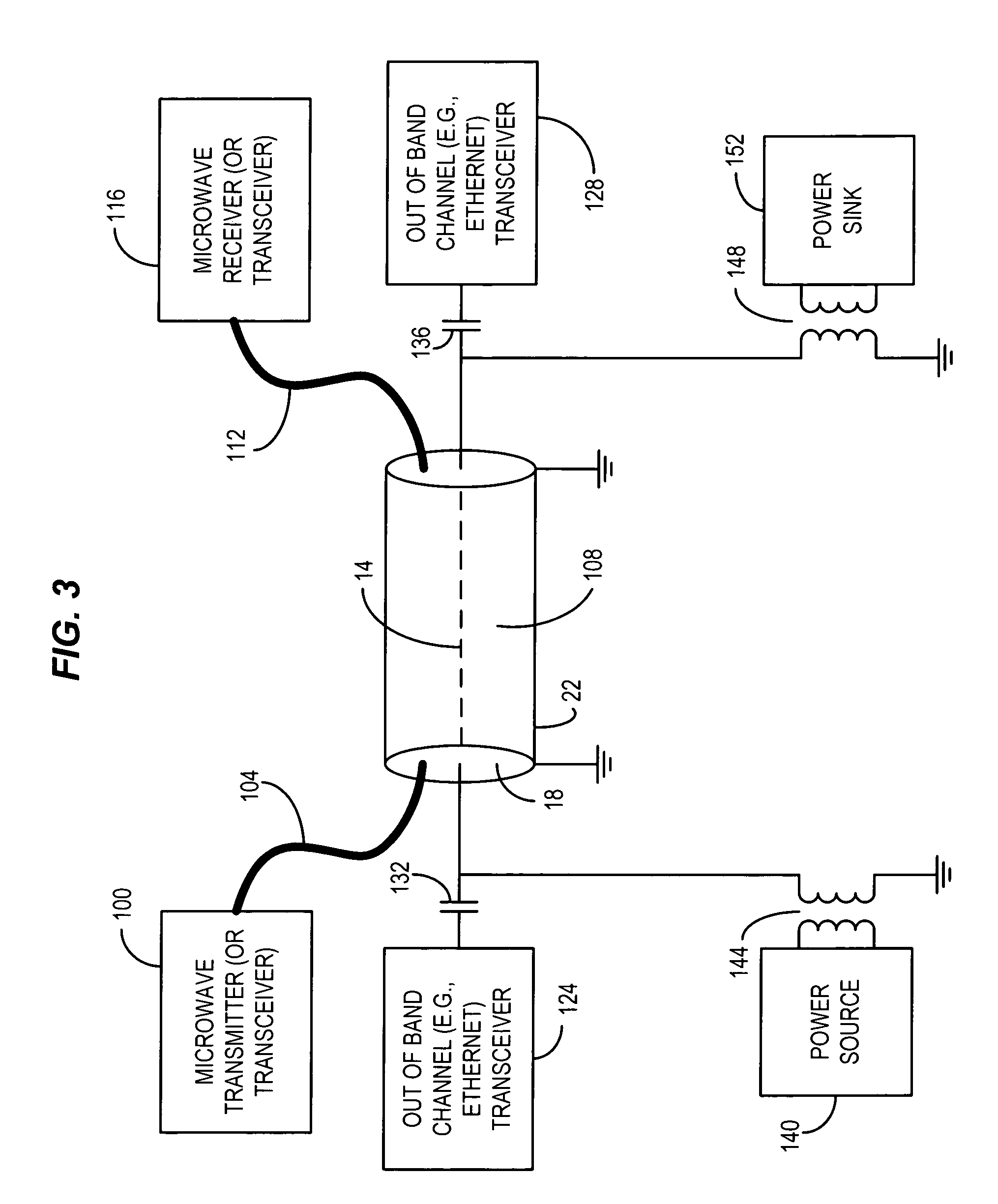
A communication device consistent with certain implementations has a coaxial cable having length and first and second ends. The coaxial cable further has a central conductor, a dielectric insulator surrounding the central conductor, and an electric shield conductor surrounding the dielectric insulator. The dielectric insulator serves as a dielectric waveguide having a characteristic impedance Z at an operating frequency range. A termination for electrical energy coupled into or out of the dielectric insulator at approximately the characteristic impedance Z at the operating frequency range to utilize the dielectric insulator as a waveguide for transmission of signals along the length of the coaxial cable, and wherein the center conductor is further used to communicate an electrical signal between the first and second ends. This abstract is not to be considered limiting, since other embodiments may deviate from the features described in this abstract.

Description

COPYRIGHT AND TRADEMARK NOTICEA portion of the disclosure of this patent document contains material which is subject to copyright protection. The copyright owner has no objection to the facsimile reproduction of the patent document or the patent disclosure, as it appears in the Patent and Trademark Office patent file or records, but otherwise reserves all copyright rights whatsoever. Trademarks are the property of their respective owners.BACKGROUNDHigh bit rate data transmission is a frequent goal of modern electronic systems such as digital televisions. This must generally be achieved at low cost and with low emissions. This has been done with multiple wires in parallel but length and emissions are a limiting factor. Optical solutions are not cost effective at this point. Free air wireless solutions have merit, but typically require substantial power.BRIEF DESCRIPTION OF THE DRAWINGSCertain illustrative embodiments illustrating organization and method of operation, together with ob...

Claims


Application Information

Patent Timeline
IPC IPC(8): H01P3/06
CPCH01P3/06H04B3/52
Inventor UNGER, ROBERT ALLANHARDACKER, ROBERT L.READ, CHRISTOPHER JENSEN
Owner SONY CORP
Why Eureka
Try Eureka