Paging control method and paging control system in communication system
a communication system and control method technology, applied in the field of paging control methods and paging control systems in communication systems, can solve the problems of inconvenient paging control of such a communication system that integrates multiple communication systems, and achieve the effect of efficient paging control
- Summary
- Abstract
- Description
- Claims
- Application Information
AI Technical Summary
Benefits of technology
Problems solved by technology
Method used
Image
Examples
first embodiment
(First Embodiment)
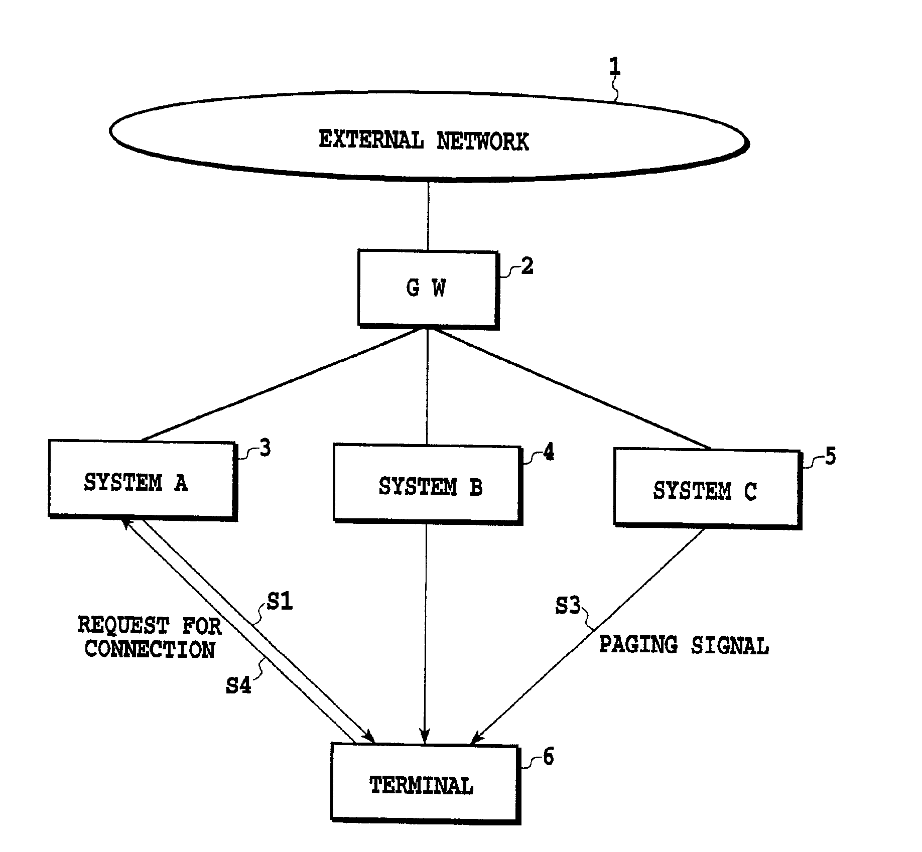
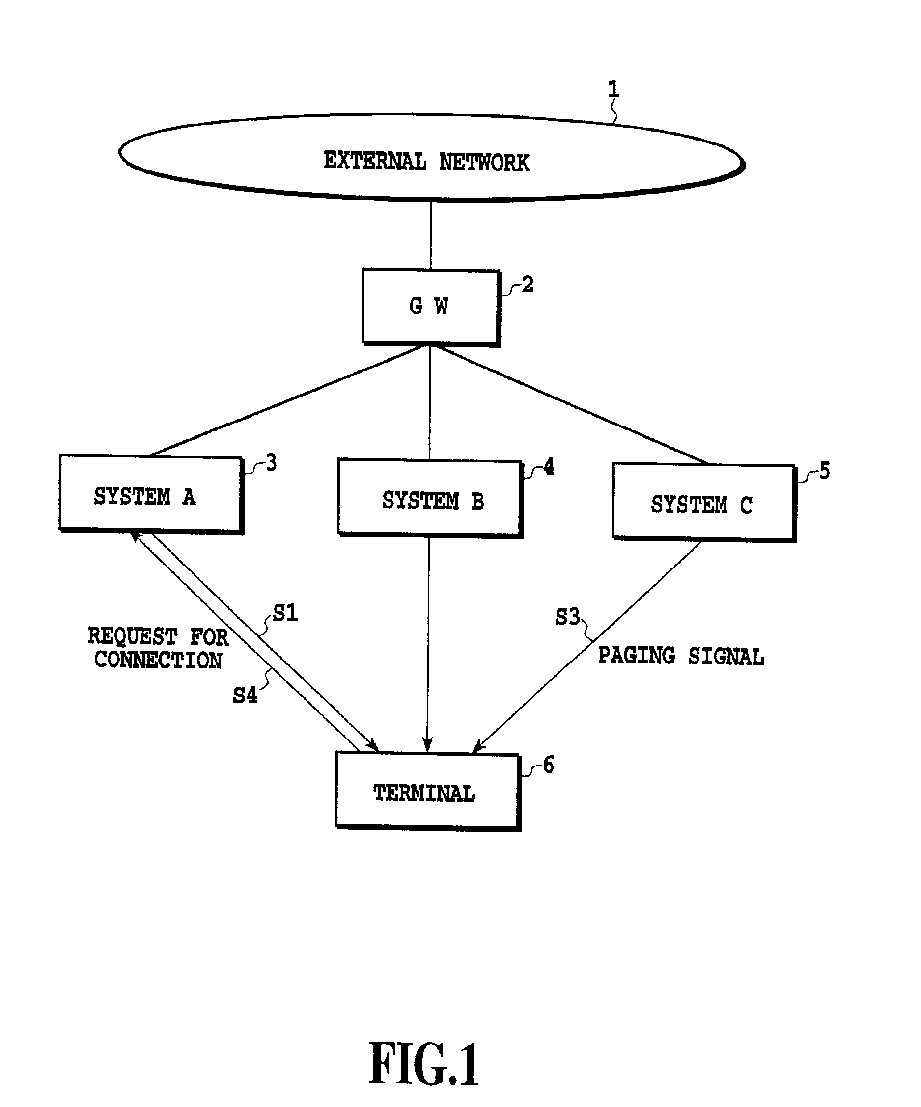
[0041]FIG. 1 is a block diagram showing a configuration of a first embodiment of the communication system in accordance with the present invention. In this figure, the reference numeral 1 designates an external network; 2 designates a gateway (GW); 3, 4 and 5 designate a communication system A, a communication system B and a communication system C, respectively; and 6 designates a terminal. It is assumed in the present embodiment that the signal from the external network 1 is transmitted to the individual communication systems 3-5 via the gateway 2. Although the communication systems 3-5 are different communication systems, they can be a wired or wireless system, and are integrated via the gateway 2.
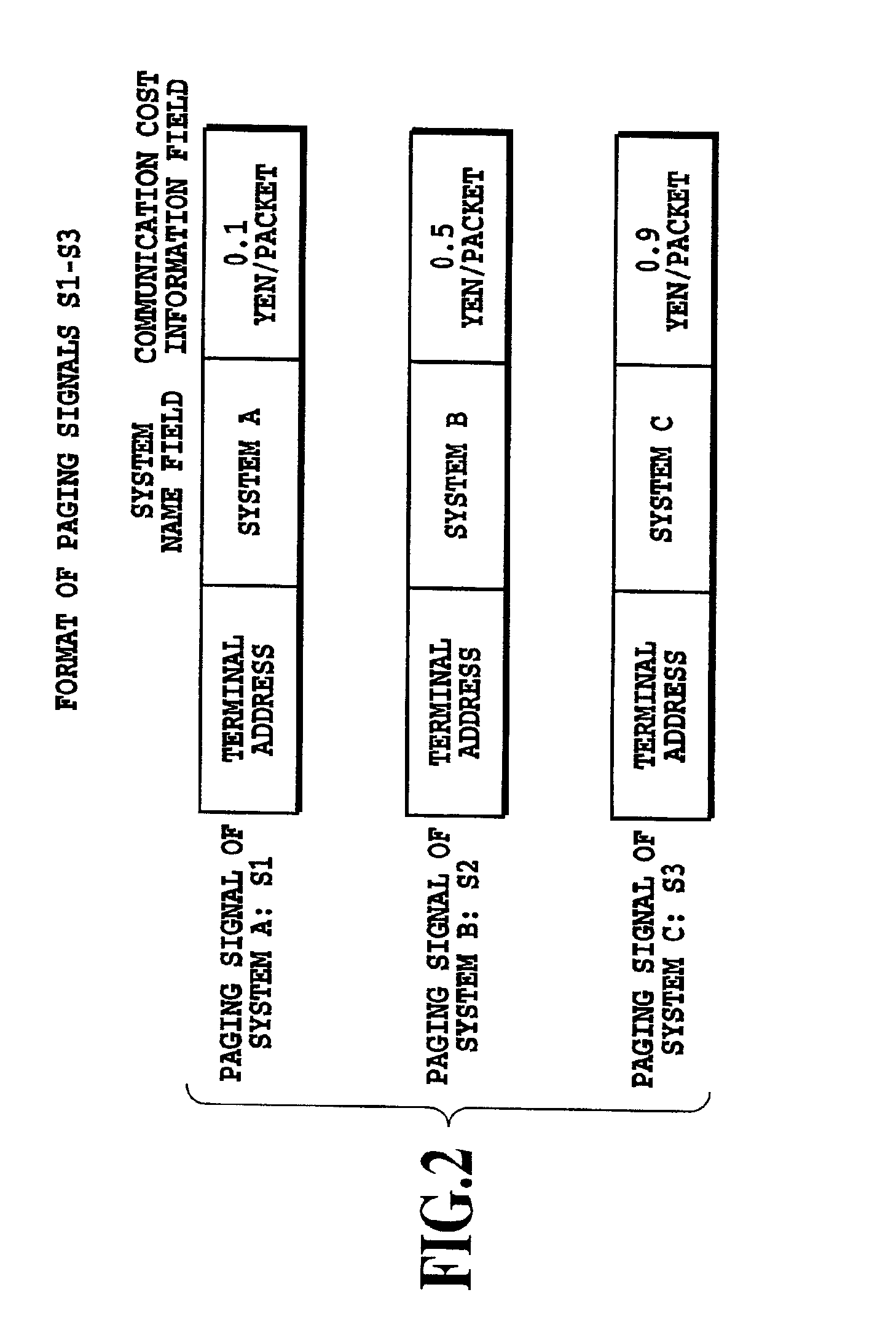
[0042]FIG. 2 is a signal format diagram illustrating an example of a paging signal transmitted from each of the communication systems 3-5 of FIG. 1. Reference symbols S1, S2 and S3 designate paging signals of the communication systems A, B and C respectively. They each ...
second embodiment
(Second Embodiment)
[0046]FIG. 3 is a block diagram showing a configuration of a second embodiment of the communication system in accordance with the present invention. In this figure, the reference numeral 7 designates a paging agent connected between the gateway 2 and the terminal 6. The paging agent 7 can recognize communication systems available for the use of each terminal 6 from the terminal location information of the terminal 6, and obtain information such as communication cost and transmission rate about the individual communication system at the terminal location. Since the remaining components are the same as those of the first embodiment described above in connection with FIG. 1, the description thereof is omitted here.
[0047]FIG. 4A illustrates an example of a signal format of a request signal S11 a terminal 6 among a plurality of terminals transmits to the paging agent 7. The request signal S11 includes a destination address field (paging agent address), a source address...
third embodiment
(Third Embodiment)
[0055]FIG. 5 is a block diagram showing a configuration of a third embodiment of the communication system in accordance with the present invention. The present embodiment is a variation of the foregoing second embodiment. Since the components of FIG. 5 are nearly the same as those of FIG. 3, the description thereof is omitted here.
[0056]The third embodiment differs from the second embodiment in that one of the communication systems is specified in advance as a system (called paging system) for transmitting a paging signal S25 to the terminal 6 as shown in FIG. 5 (in this case the communication system B 4). The paging system sends to the terminal 6 the optimum communication system name selected by the paging agent 7, that is, the communication system name (communication system A 3, for example) to be used for actually transmitting the information signal, with containing in the paging signal S25. The remaining operation is nearly the same as that of the second embodi...
PUM
 Abstract
Description
Claims
Application Information
 - R&D
- Intellectual Property
- Life Sciences
- Materials
- Tech Scout
- Unparalleled Data Quality
- Higher Quality Content
- 60% Fewer Hallucinations
Browse by: Latest US Patents, China's latest patents, Technical Efficacy Thesaurus, Application Domain, Technology Topic, Popular Technical Reports.
© 2025 PatSnap. All rights reserved.Legal|Privacy policy|Modern Slavery Act Transparency Statement|Sitemap|About US| Contact US: help@patsnap.com


