
Strapping machine with paddle formed strap path

a strap path and strap machine technology, applied in the field of strap machines, can solve the problems of difficult access to the strap path from the supply to and around the chute, and many of the strap paths of these machines are quite larg

Active Publication Date: 2005-08-02
SIGNODE IND GRP
View PDF5 Cites 18 Cited by
  • Summary
  • Abstract
  • Description
  • Claims
  • Application Information

AI Technical Summary

Benefits of technology

[0024]FIG. 6 is an exploded view of the control system enclosure;
[0025]FIG. 7 is a view of the control system enclosure of FIG. 6 assembled;
[0026]FIG. 8 is a top perspective view of the upper corner of one of the enclosure panels (doors) and the frame, showing the upper hinge pintle and the quick-release latch;
[0027]FIG. 9 is a top view of the quick-release latch of FIG. 8;

Problems solved by technology

One drawback to known plastic strap tabletop strappers is that the strap path from the supply to and around the chute can be difficult to access.
Another drawback is that physically, many of these machines are quite large.

Method used


Image

  • Strapping machine with paddle formed strap path
  • Strapping machine with paddle formed strap path
  • Strapping machine with paddle formed strap path

Examples


Embodiment Construction

[0047]While the present invention is susceptible of embodiment in various forms, there is shown in the drawings and will hereinafter be described a presently preferred embodiment with the understanding that the present disclosure is to be considered an exemplification of the invention and is not intended to limit the invention to the specific embodiment illustrated.

[0048]It should be further understood that the title of this section of this specification, namely, “Detailed Description Of The Invention”, relates to a requirement of the United States Patent Office, and does not imply, nor should be inferred to limit the subject matter disclosed herein.

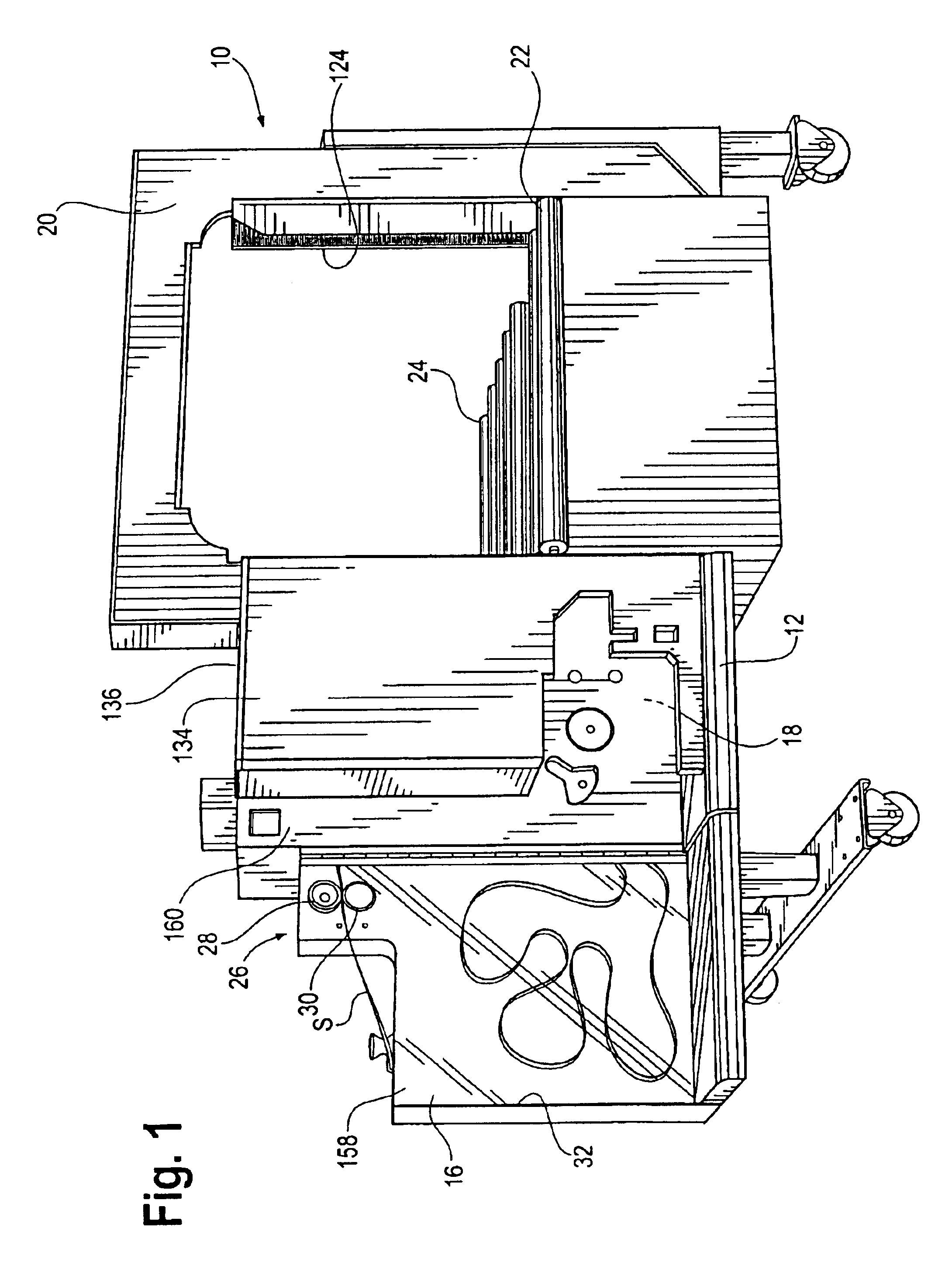
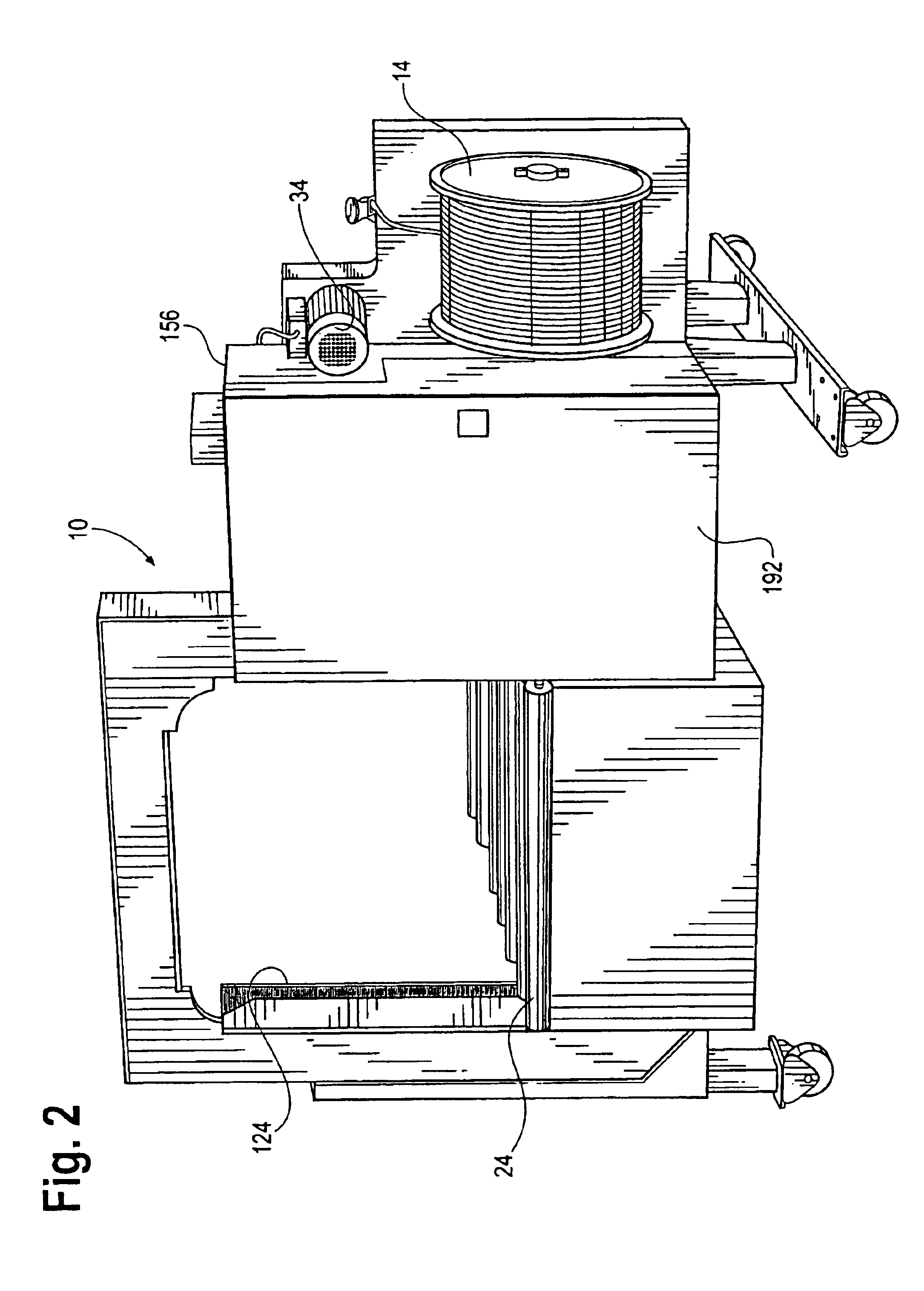
[0049]Referring now to the figures and in particular to FIGS. 1-2, there is shown an improved strapping machine 10 embodying the principles of the present invention. The machine 10 includes, generally, a frame 12, a strap supply such as the illustrated dispenser 14, a slack box 16, a strapping head 18 and a strap chute 20. The machine 10...


PUM


Abstract

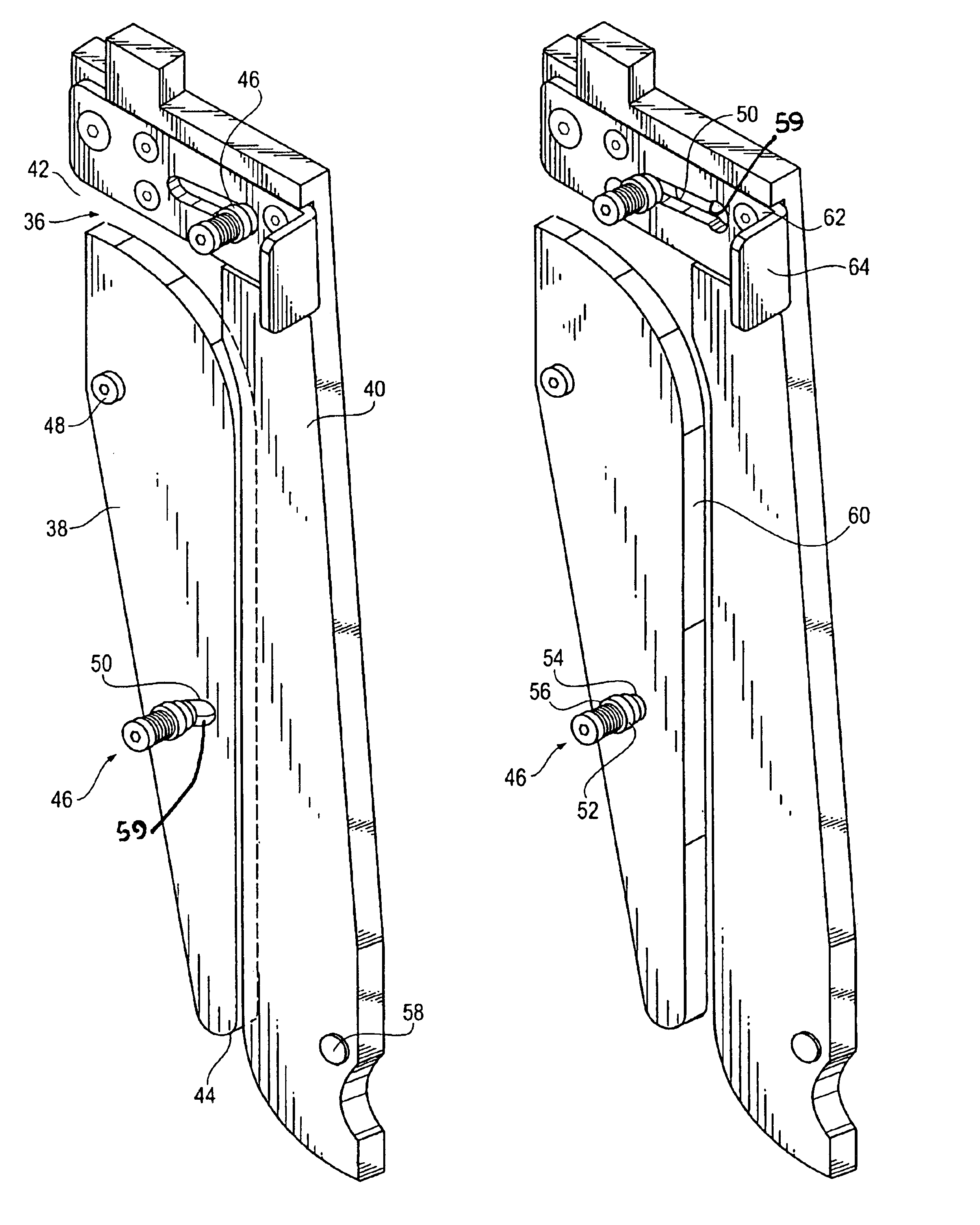
A strapping machine for positioning a strap material around an associated load, tensioning the strap material and sealing the strap material to itself around the load, the strapping machine includes a strap path formed from opposing, movable elements. The machine includes a frame, a slack box, and a first portion of a strap path from the slack box. The first portion of the strap path is formed by a pair of opposing path forming elements moveable toward and away from each other between an open path position and a closed path position. The path forming elements further define a path entrance and a path exit, The closed path position defines the first portion of the strap path. A strapping head is mounted to the frame and is configured to convey the strap material in a first direction to position the strap material around the load and to convey the strap material in a second direction to tension the strap material around the load. The strapping head is further configured to seal the strap material to itself and to sever the strap material from a strap supply. A chute defines a second portion of the strap path, the chute is mounted to the frame and is configured to provide a path to position the strap material around the load.

Description

CROSS-REFERENCE TO RELATED APPLICATION DATA[0001]This application claims the benefit of priority of U.S. Provisional Patent Application Ser. No. 60 / 429,640, filed Nov. 27, 2002.BACKGROUND OF THE INVENTION[0002]The present invention pertains to a strapping machine. More particularly, the present invention pertains to a strapping machine having an improved, readily accessible strap path that is formed by movable, opposing paddles.[0003]Strapping machines are well known in the art. These machines, also referred to as strappers, are used for positioning, tensioning and sealing a strap around a load. The strapping machines are used for a wide variety of objects from piles of lumber to newspapers and magazines to bales of hay and cotton.[0004]Strapping machines are of two types, namely hand-held models and table top models. These machines can be made for use with metal or plastic straps.[0005]In a typical, tabletop plastic strapping machine, the overall machine is mounted to a stationary ...

Claims


Application Information

Patent Timeline
Patent Type & Authority Patents(United States)
IPC IPC(8): B65B13/06B65B13/00B65B13/18
CPCB65B13/06B65B13/18B65B13/185
Inventor BOBREN, ALLAN J.PEARSON, TIMOTHY B.
Owner SIGNODE IND GRP
Learn More