Side nail puller

a nail pulling device and side nail technology, applied in the direction of lifting devices, hand hammers, crowbars, etc., can solve the problems of insufficient leverage of conventional claw hammers, difficult nail positioning near the end of boards, etc., and achieve the effect of not adding significant cost or complexity

Active Publication Date: 2005-08-02
MILWAUKEE ELECTRIC TOOL CORP
View PDF17 Cites 40 Cited by
  • Summary
  • Abstract
  • Description
  • Claims
  • Application Information

AI Technical Summary

Benefits of technology

[0012]The advantages of the present invention include that nails may be removed using a hammer in a simple and intuitive manner. The nail puller may be incorporated into hammer designs without adding significant cost or complexity.

Problems solved by technology

For example, a nail positioned near the end of a board may be difficult to remove because there may not be enough room at the end of the board for a conventional claw hammer.
Further, the leverage of a conventional claw hammer may be insufficient to remove difficult nails, such as long nails in hardwoods.

Method used


Image

  • Side nail puller
  • Side nail puller
  • Side nail puller

Examples


embodiment 100

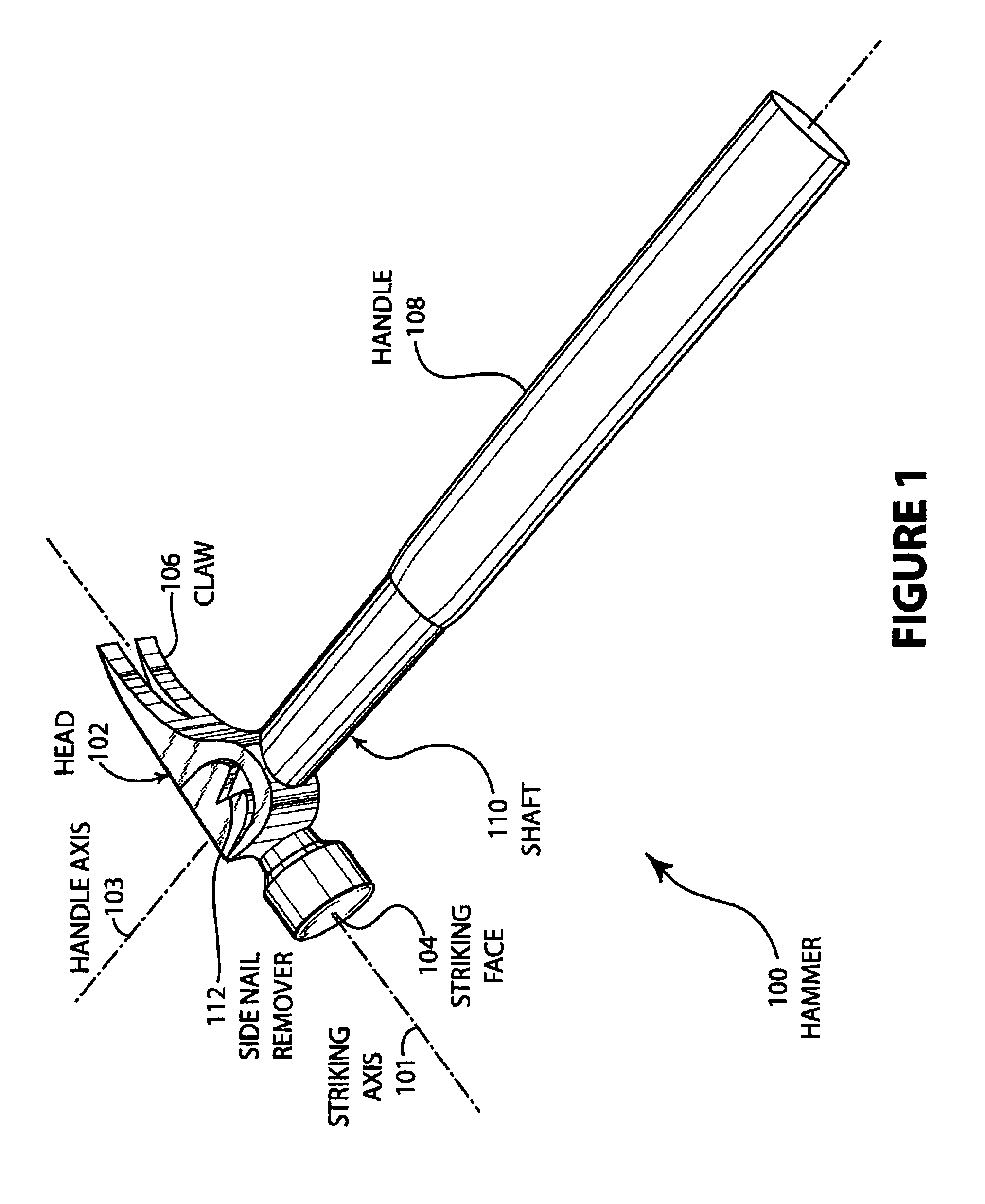
[0022]FIG. 1 illustrates an embodiment 100 of the present invention showing a hammer 100 having a head 102 that has a striking face 104 and claw 106. The handle 108 extends from the head 102. The handle shaft 110 is integral to the head 102. The head 102 contains a side nail remover 112. The striking axis 101 and handle axis 103 are shown approximately perpendicular to the striking face 104 and approximately parallel to the shaft 110, respectively.

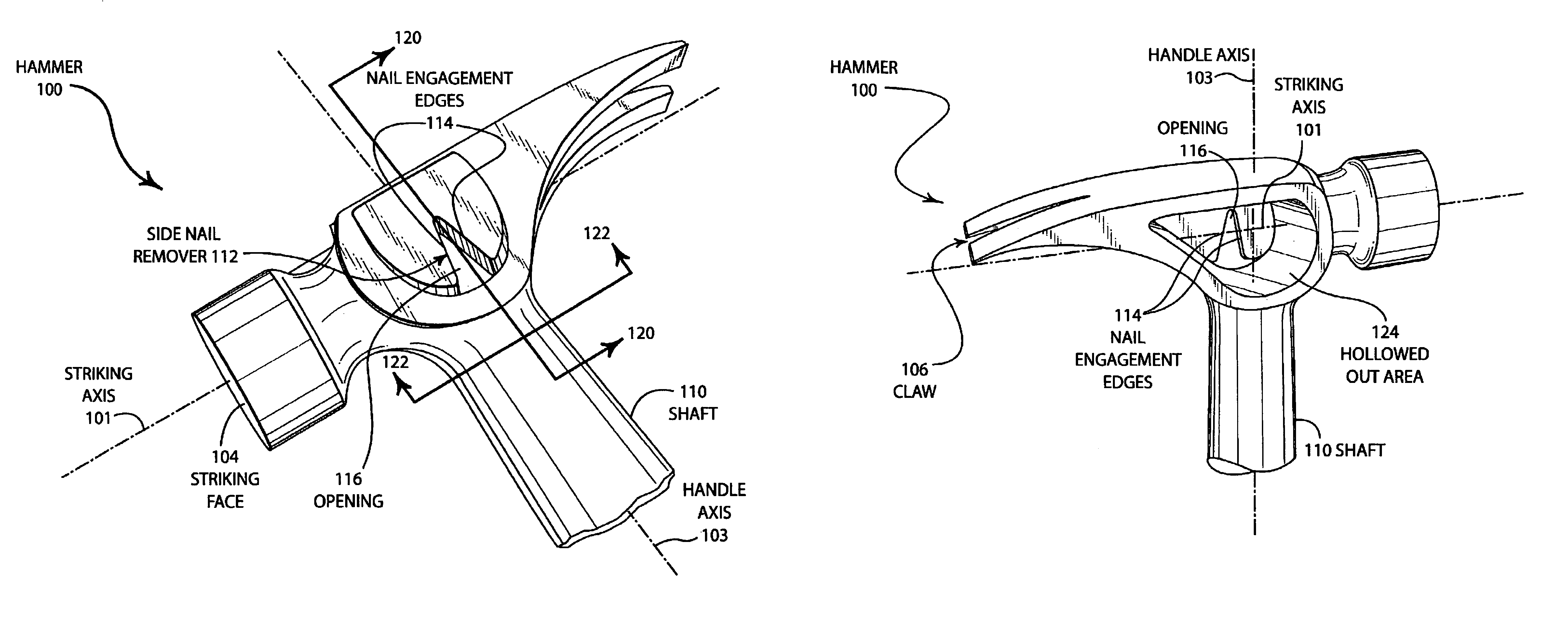
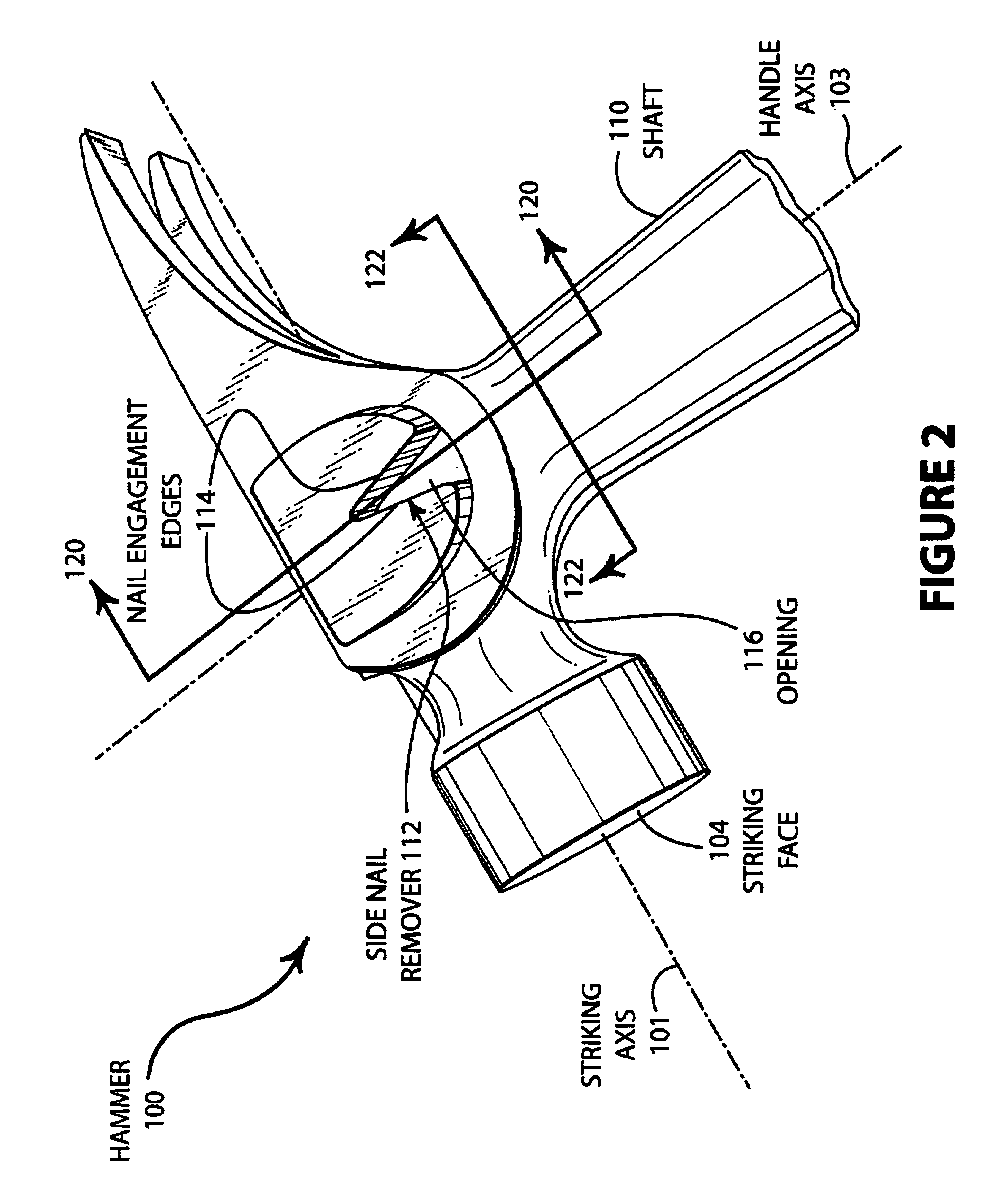
[0023]FIG. 2 illustrates a closer view of embodiment 100 of a hammer. The striking face 104, shaft 110, and side nail puller 112 are shown.

[0024]The nail puller 112 is comprised of two nail engagement edges 114 and the opening 116. The opening 116 is designed to allow the head of a nail fit inside the opening, and the tapered configuration of the nail engagement edges 114 allows the hammer 100 to be slid over the nail until the shank of the nail is grasped by the edges 114. Once the nail is engaged, the hammer 100 may be rotated about an a...

first embodiment

[0034]FIG. 4A illustrates a cross-sectional view 120 from FIG. 1. The shaft 110 is shown in cross-section along with the striking plane 126. The nail engagement edge 114 is shown as well as the hollowed out area 124.

[0035]The striking plane 126 is the approximate center plane of the striking tool and the plane in which the tool is swung to strike an object. The nail engagement edge 114 is shown slightly canted upward in the illustration, but generally parallel to the striking plane 126. In some embodiments, the nail engagement edge 114 may be very close to parallel to the striking plane 126.

second embodiment

[0036]FIG. 4B illustrates a cross-sectional view 120 from FIG. 1. The shaft 110 is shown in cross-section along with the striking plane 126. The nail engagement edge 114 is also shown as well as the hollowed out are 124.

[0037]The nail engagement edge 114 is curved upward in a convex manner, when viewed from the working surface. The convex shape of nail engagement edge 114 may allow the side nail puller 112 to dig into a substrate, such as wood, and engage a nail head. The shape may be a similar design as for a ‘cat's paw’ or similar nail extracting tools.

[0038]FIG. 5A illustrates a first embodiment of a cross-sectional view 122 from FIG. 1. The shaft 110 is shown in cross-section along with the striking plane 126. The nail engagement edges 114 are formed by the surface 128, which is substantially flat.

[0039]FIG. 5B illustrates a second embodiment of a cross-sectional view 122 from FIG. 1. The shaft 110 is shown in cross-section along with the striking plane 126. The nail engagement ...


PUM


Abstract

A nail puller mounted on the side of the head of a hammer. The nail puller may be incorporated into a metal hammer head and consist of a groove mounted substantially in line with the handle of the hammer. The nail puller consists of a V-shaped opening suitable for engaging various sizes of nail heads or shanks. The nail puller is located on the side of the hammer, such that the nail is engaged when the hammer is laid nearly parallel to the work surface. The position of the nail puller gives the user nearly 180 degrees of rotation to remove the nail.

Description

BACKGROUND OF THE INVENTION[0001]a. Field of the Invention[0002]The present invention pertains generally to nail pulling devices and specifically to nail pulling devices incorporated into a hammer or other striking tool.[0003]b. Description of the Background[0004]A hammer is the most ubiquitous tool of the carpentry trade. Carpenters use hammers to both drive and remove nails. Carpenters are also known for their creativity and ability to use tools in various ways to solve problems as they come up. For example, even though a traditional claw hammer may have a conventional striking face, a carpenter may use the side of the hammer to drive a nail or strike a tool in specific instances. The more options a carpenter has for using a tool, the more the tool will be used.[0005]Removing nails is a task for which a carpenter may use several different tools, including a claw hammer, a “cat's paw” nail remover, various pry bars, and other tools. Each tool is suited to specific applications depe...

Claims


Application Information

Patent Timeline
Patent Type & Authority Patents(United States)
IPC IPC(8): B25C11/00B25D1/04
CPCB25D1/045
Inventor MARTINEZ, MARK
Owner MILWAUKEE ELECTRIC TOOL CORP
Why Eureka
Try Eureka