[0011] The
image content comprises a plurality of image elements which can be stretched or compressed in dependence on the shape of the electronic image. To reduce distortions of the image projected onto the projection surface or to represent intentionally distorted images, the image lines are processed using a processing device so that the electronic image is altered particularly geometrically. Under consideration of all image lines, which before may possibly have been processed only partially, the
image content of the electronic image is newly computed by means of a computing device. The newly computed electronic image is then visualized through a representation device; this representation device can be e.g. a monitor of an image processing device used for this purpose, or a
projector such as, e.g., a video beamer.
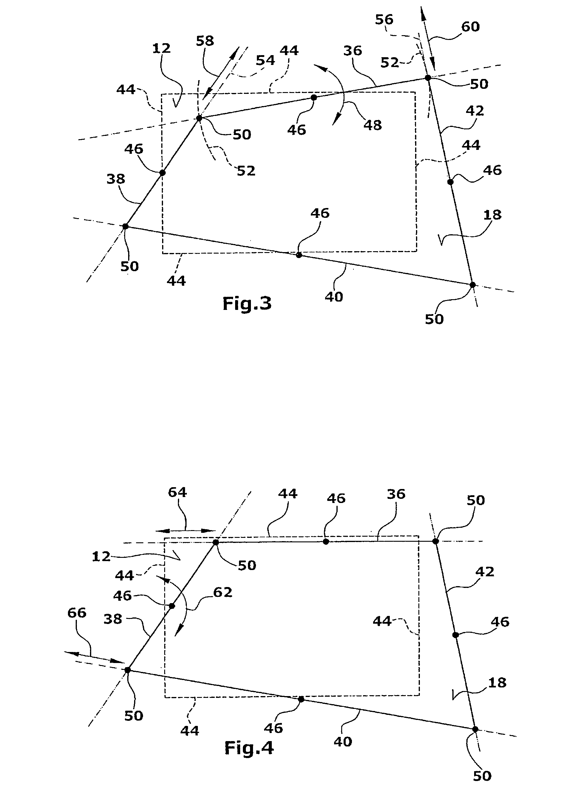
[0013] Since the orientation of the other image lines is maintained, the processing of the electronic image can be carried out in a very simple and intuitive manner. For a keystone correction of an image projected onto a projection surface, it will be sufficient if the individual image lines are aligned one after the other in the desirable orientation for the viewer. For instance, the image edges of a rectangular electronic image which has been perspectively distorted by the projection are successively oriented horizontally and vertically, respectively, and are subjected to this orienting process until right angles are obtained between two adjacent edges of the image. In an e.g. rectangular electronic image, it is also possible to orient the image edges with reference to the edges of a screen, the edges defining the projection surface. Further, the image edges of the electronic image can be oriented with reference to markers applied to a wall. Particularly, it made possible to have the projected image represented to the viewer in an undistorted manner irrespective of whether or not the direction of the representation and / or the projection surface is arranged obliquely relative to a viewer. Knowledge of a concrete angle at which the projected image is incident on the projection face and of the concrete distance of the representation device to the projection surface is not required. Further, it is not necessary anymore to perform several subsequent correction steps. As a result, the keystone correction is simplified and can be performed in less time.
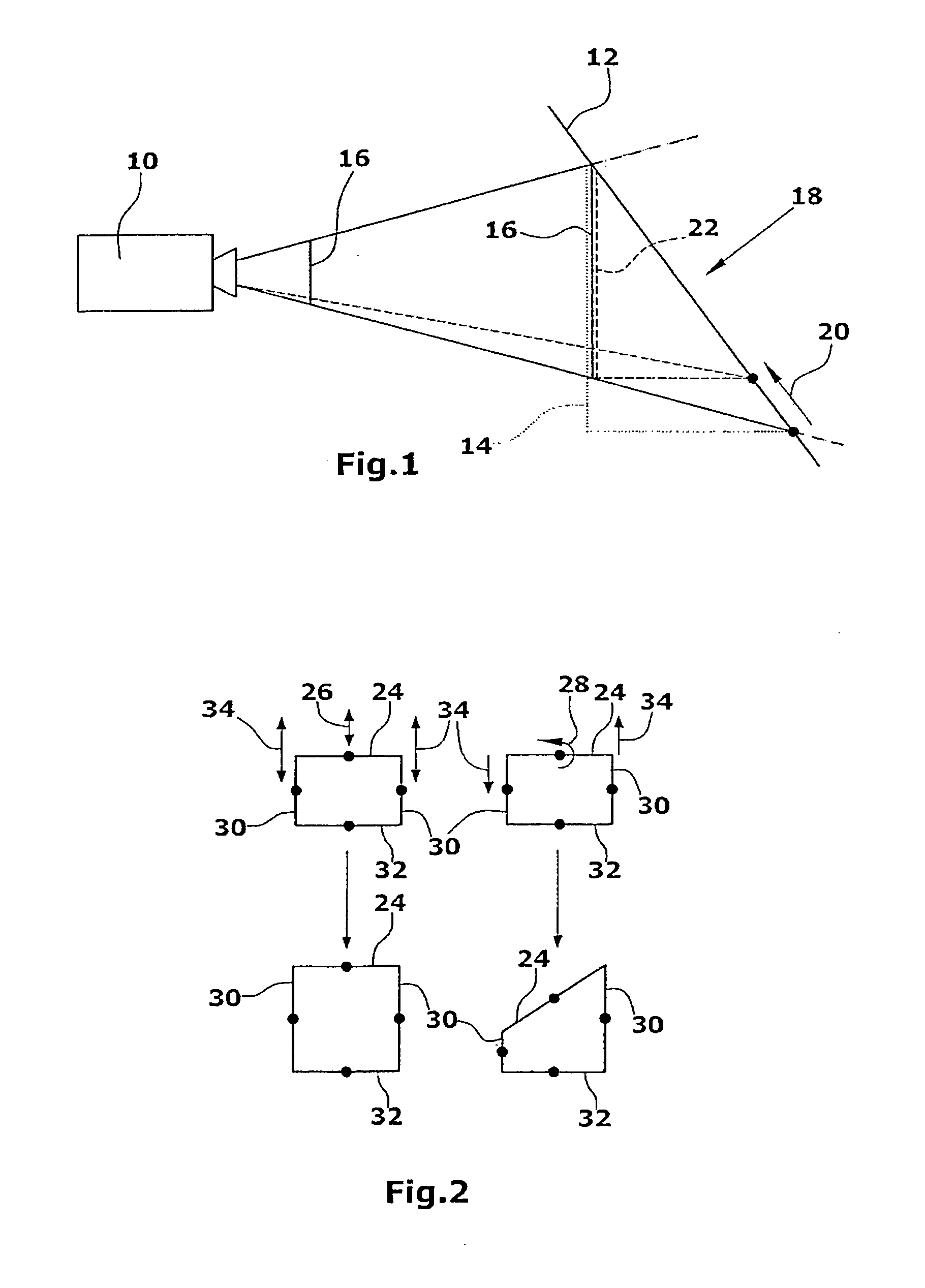
[0014] According to an independent invention, the image lines of the original electronic image comprise a plurality of partial sections of equal lengths, which, according to the invention, can be differently stretched and / or compressed by the processing device during the processing procedure. Thereby, the concentration of the image elements within the electronic image is varied, while the overall length of the image lines is maintained. Particularly, the different stretching / compressing as provided by the invention can be performed independently of other processing procedures performed on the image lines, i.e. a processing of respectively one image line each time is not positively necessary for this purpose. The different stretching / compressing of the partial sections can also be carried out in combination with keystone corrections corresponding to the trapezoidal distortion or corresponding to the free displacement of corner points. In this manner, it is possible to compensate for the perspective distortion within the projected image resulting from the different lengths of the projection beams onto a projection surface. Accordingly, the different stretching and compressing, respectively, of the individual image elements of the
image content can be corrected for or deliberately brought about. Thereby, particularly, even extremely tilted positions of a projector relative to a projection surface are made possible, allowing virtually any desired orientation of the projector relative to the projection surface. It is not required to know the angle at which the projected image impinges on the projection surface or to know the distance from the projector to the projection surface. Thus, image projections can be realized also in rooms where several—possibly shadow-
casting—objects are located since the projector can be oriented in a direction passing by the objects, e.g. at a steep angle from above. Further, the quality of the keystone correction is distinctly improved.
[0015] During the stretching / compressing of the partial sections, the overall length of the image lines is preferably maintained. Thereby, within an image line which is kept constant, the processing device will change the
length distribution of the individual sections. Particularly, the length ratio of two adjacent partial sections is set to be identical for all partial sections. Thus, the
length distribution of the partial sections is made uniform. Further, for the stretching and compressing of the individual partial sections, there is thus generated a common parameter which, when manipulated by the processing device, allows for a very simple keystone correction. Particularly, in case of uneven projection surfaces, the length ratios of two adjacent partial sections can be set to different values. For instance, in case of a cylindrical projection surface, the length ratio of the partial sections in the outer regions of the cylinder can be identical while increasing or decreasing towards the center.
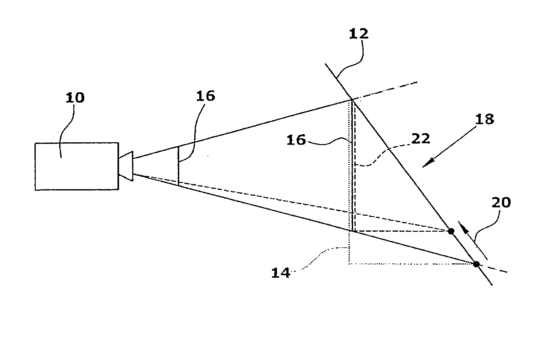
[0016] Preferably, the projection surface is provided with projection lines which define the shape of the projection surface. The projection lines can be e.g. the lateral edges of a screen or markers on a plane surface which indicate the position and the size that the projected image is desired to have. In this manner, it is possible, when processing the image lines, to rotate and / or shift the image line until the image lines are oriented relative to the projection lines, thus effecting a keystone correction in an especially simple manner. Particularly, it is possible to adjust the image edges of a to-be-projected rectangular image in a manner causing them to be arranged directly above the lateral edges of a screen or respectively equidistantly to these edges.

