Stripping means for milling rolls of a construction machine as well as a construction machine and a method

a technology of construction machines and rolling pins, which is applied in the direction of cutting machines, roads, constructions, etc., to achieve the effect of low mounting efforts and low cos

Inactive Publication Date: 2005-08-02
WIRTGEN GMBH
View PDF3 Cites 42 Cited by
  • Summary
  • Abstract
  • Description
  • Claims
  • Application Information

AI Technical Summary

Benefits of technology

[0008]Therefore, it is the object of the invention to provide a stripping means for milling rolls of a construction machine, an automotive construction machine, particularly a road milling machine, as well as a method, by means of which an adaptation to the milling roll width is possible in a flexible manner, at low costs and at low mounting efforts.
[0014]It is particularly advantageous that the stripping means can be adapted to the respectively used milling roll of different milling widths, different milling roll contours and different milling roll positions at low mounting efforts, whereby only the lower stripper portion has to be exchanged.
[0018]In a preferred embodiment, it is provided that the mounting means carries a lower stripper portion extending over the entire milling width as well. When a milling roll with maximum milling width is used, it is therefore possible to use the stripping means with the stripping blade and the lower stripper portion as a second stripping blade and set both stripping blades upon the milled surface. In doing so, the first stripping blade can be operated at a lower contact pressure. Due to the fact that the milled surface is stripped double, a higher degree of cleanliness can be achieved.
[0021]The lower stripper portion may comprise at least one opening for the defined deposition of the milled-off material. The opening consists of a recess downwardly open by means of which specifically milled-off material can be deposited in the form of strips on and / or next to the milled surface. If milled-off material is to be deposited next to the milled surface, the lower stripper portion may comprise a laterally projecting section arranged at a distance from the surface to be milled in order to deposit the milled-off material. Generally, the contour of the lower stripper portion can be chosen freely so that a quick adaptation to different objectives can be effected because of the quick exchangeability of the lower stripper portion.

Problems solved by technology

There is the disadvantage that due to the fixed width of the segments, only milling rolls with a width corresponding to the segmentation of the stripping blade segments are applicable.

Method used


Image

  • Stripping means for milling rolls of a construction machine as well as a construction machine and a method
  • Stripping means for milling rolls of a construction machine as well as a construction machine and a method
  • Stripping means for milling rolls of a construction machine as well as a construction machine and a method

Examples


Embodiment Construction

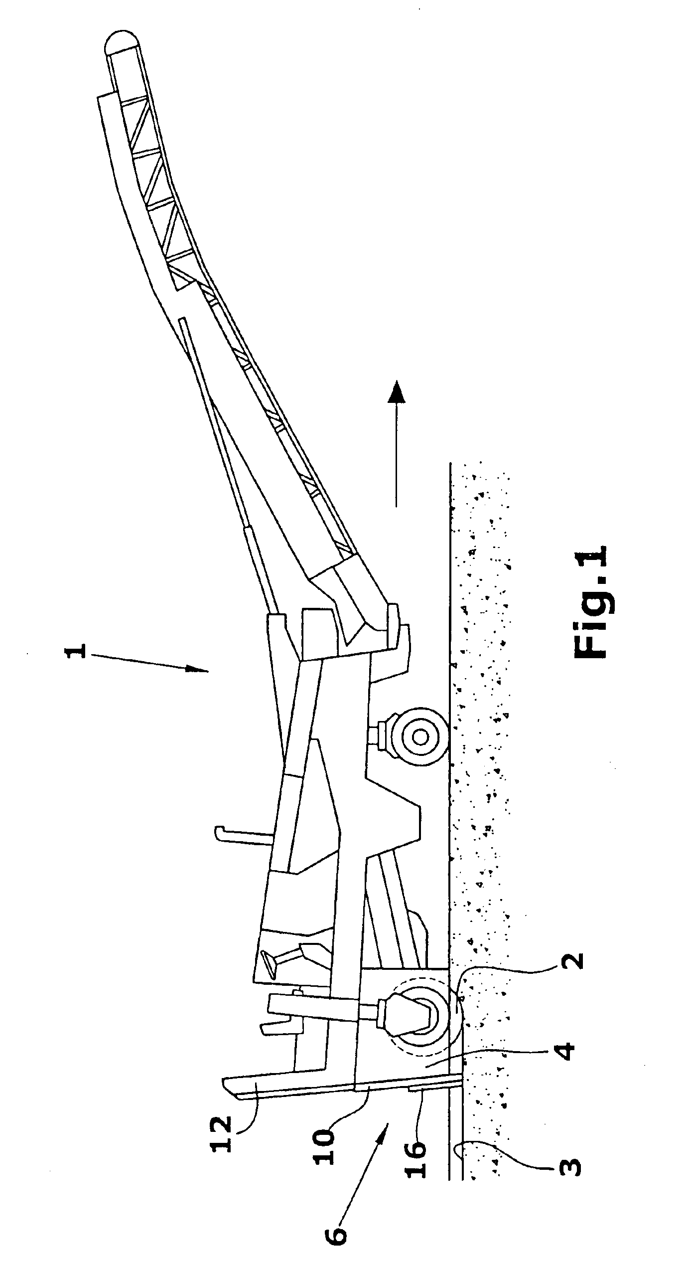
[0040]FIG. 1 shows the application of the invention with a front loader road milling machine.

[0041]Such road milling machines 1 may be provided with a quick change system for the milling rolls by means of which a change of the milling roll 2 is possible within a short time and at low mounting efforts. Thereby, different orders can be worked with the same road milling machine.

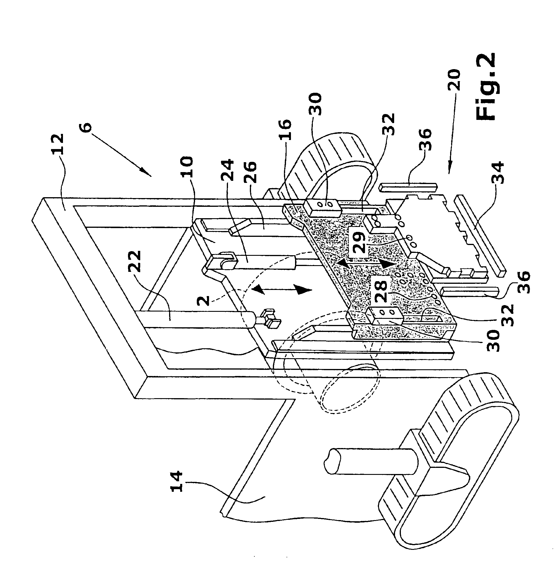
[0042]In FIG. 1, the automotive road milling machine 1 is equipped with wheels, but it may of course be also supported by chain running gears as shown in FIG. 2.

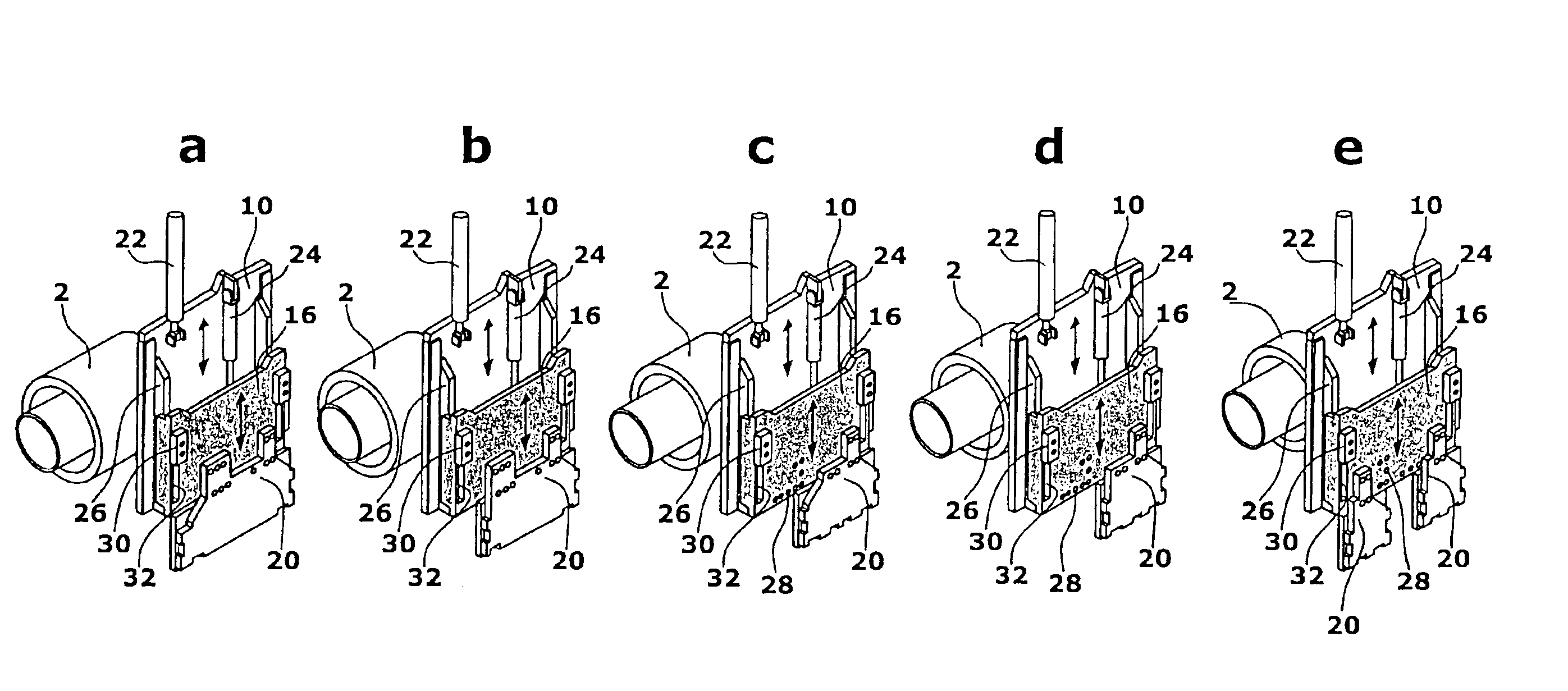
[0043]In the embodiment of the road milling machine 1 according to FIG. 1, the milling roll 2 is arranged at the rear end of the machine and surrounded by a roll box 4. At the rear end of the roll box 4 in traveling direction, a stripping means 6 that is adjustable in height is arranged, comprising a stripping blade 10 covering the maximum milling width of the widest milling roll 2 and being guided in a height-adjustable manner, for example, in a portal ...


PUM


Abstract

In a stripping means for milling rolls (2) of a construction machine, comprising at least one stripping blade (8) arranged behind the milling roll (2) in traveling direction so as to be adjustable in height, which is able to glide over the surface (3) milled or to be milled by the at least one milling roll (2), it is provided that the stripping blade (10) covers the maximum milling width, and that a mounting means (16) adjustable in height relative to the stripping blade (20) is arranged for at least one lower stripper portion (20) adapted to the respectively used milling roll (2) or milling rolls, the lower stripper portion (20) being able to be positioned, by means of the mounting means (16), in a position corresponding to the milling roll (2) within the width of the stripping blade (10).

Description

BACKGROUND OF THE INVENTION[0001]1. Field of the Invention[0002]The invention relates to a stripping means for milling rolls on a construction machine, an automotive construction machine, particularly a road milling machine and the method thereof.[0003]2. Description of Related Art[0004]Road milling machines are known wherein milling rolls of different milling widths are applicable within a maximum milling width. A transporting means for transporting the milled-off material is located in front of or behind the milling roll in the traveling direction thereof. Behind the millling roll in the traveling direction thereof, a stripping blade is arranged in a height-adjustable manner, said stripping blade being able to glide over the surface milled by the milling roll and clean this surface from the remaining milled-off material.[0005]Particularly with road milling machines permitting a quick exchange of milling rolls of different milling width, it is desirable that the stripping blade is ...

Claims


Application Information

Patent Timeline
Patent Type & Authority Patents(United States)
IPC IPC(8): E01C23/088E01C23/00E01C23/09E02F3/76E02F3/815
CPCE01C23/088E01C23/0913E02F3/76E02F3/7695E02F3/815
Inventor HOLL, BERNDLEY, HERBERTHAEHN, GUENTHER
Owner WIRTGEN GMBH
Why Eureka
Try Eureka