Plate locking system for mated electrical connectors and methods thereof

Inactive Publication Date: 2005-08-02
ANDERSON POWER PRODS
View PDF15 Cites 7 Cited by
  • Summary
  • Abstract
  • Description
  • Claims
  • Application Information

AI Technical Summary

Benefits of technology

[0007]The present invention provides a complete and integrated locking system for electrical connectors which prevents the electrical connectors from coming apa

Problems solved by technology

Unfortunately, one of the problems with existing electrical connectors, such as Euro D

Method used


Image

  • Plate locking system for mated electrical connectors and methods thereof
  • Plate locking system for mated electrical connectors and methods thereof
  • Plate locking system for mated electrical connectors and methods thereof

Examples


Example

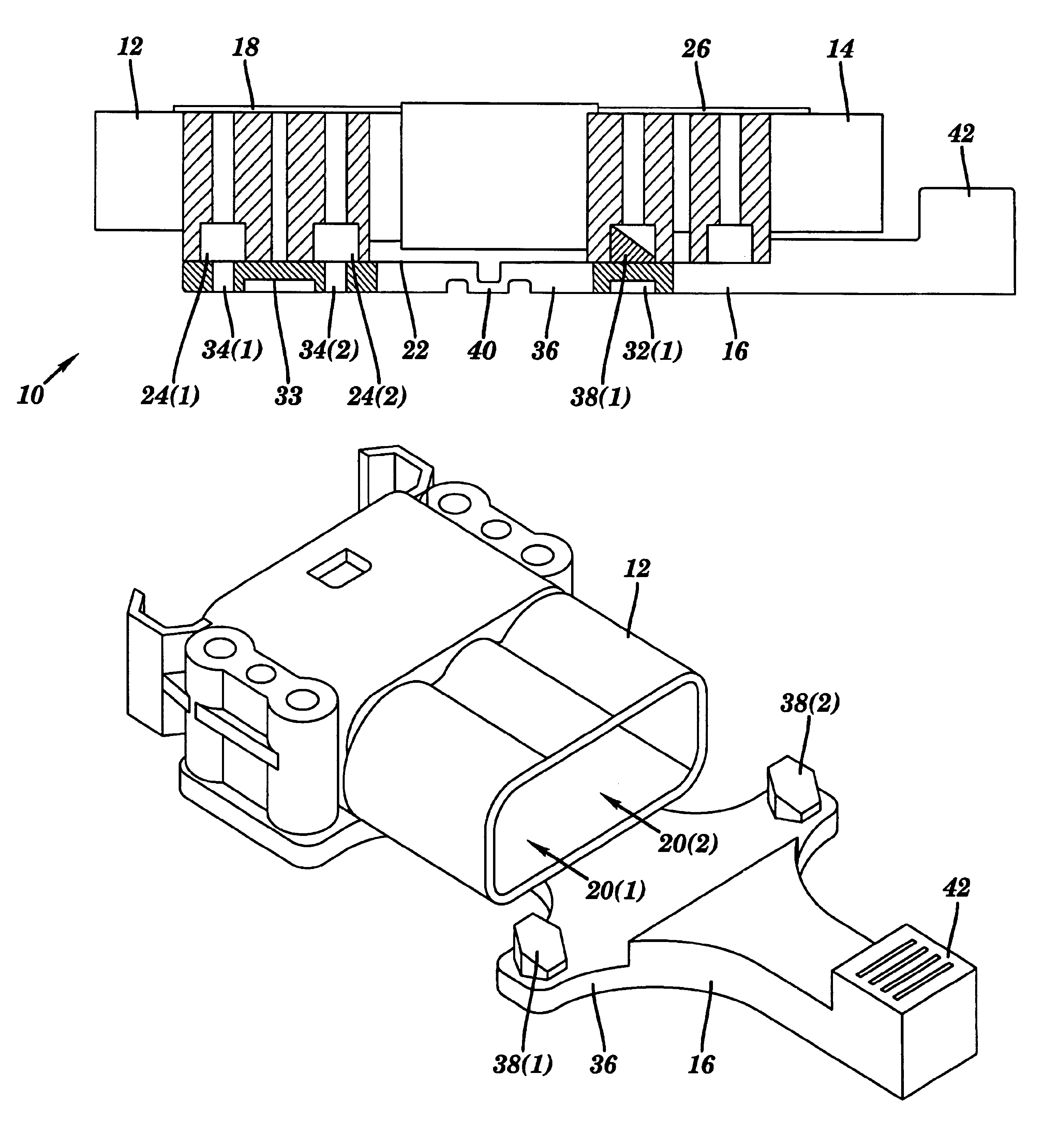
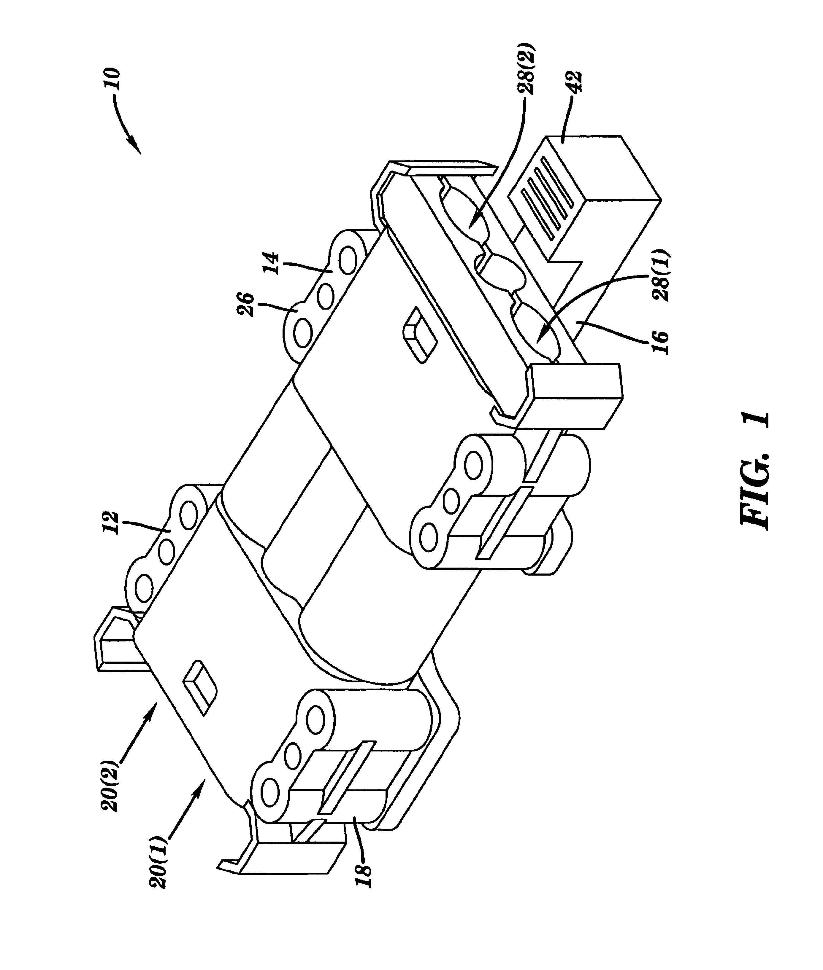
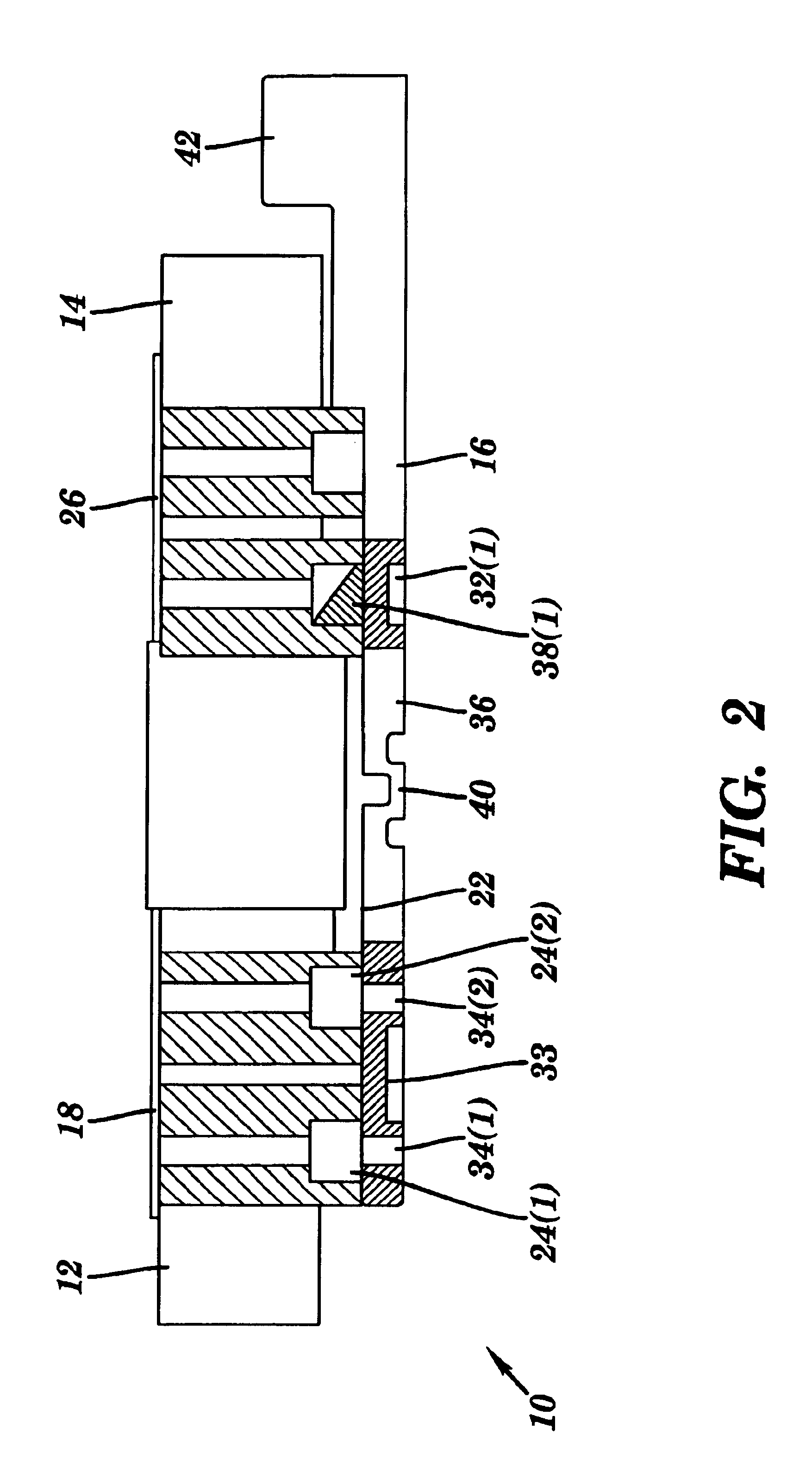
[0017]An electrical connection system 10 in accordance with an embodiment of the present invention is illustrated in FIGS. 1-5E. The electrical connection system 10 includes a first electrical connector 12, a second electrical connector 14, and a locking plate 16, although the electrical connection system 10 may comprise other types, numbers, and combinations of components. The present invention provides a number of advantages including providing a complete and integrated locking system for electrical connectors with a quick release system.

[0018]Referring to FIGS. 1-3, the first electrical connector 12 include a first housing 18 with first passages 20(1) and 20(2) to receive and secure a first pair of electrical leads, although the number and shapes of first passages 20(1) and 20(2) to receive first electrical leads can vary and the first electrical leads can be coupled to the first housing 18 in other manners. Since the manner in which electrical leads are secured and coupled to an...


PUM


Abstract

An electrical connection system includes a first electrical connector, a second electrical connector, and a locking plate. The second electrical connector having one of a projecting boss and a boss opening. The locking plate is connected to the first electrical connector and has the other one of the projecting boss and the boss opening. The engagement of the boss with the boss opening locks the second electrical connector to the first electrical connector.

Description

[0001]This application claims the benefit of U.S. Provisional Patent Application Ser. No. 60 / 404,566 filed Aug. 19, 2002, which is herein incorporated by reference in its entirety.FIELD OF THE INVENTION[0002]This invention relates generally to electrical connectors and, more particularly, a plate locking system for mated electrical connectors.BACKGROUND OF THE INVENTION[0003]A variety of different types of electrical connectors are used to couple electrical leads together. Unfortunately, one of the problems with existing electrical connectors, such as Euro DIN connectors, is that with vibration the electrical connectors can easily disconnect.SUMMARY OF THE INVENTION[0004]An electrical connection system in accordance with embodiments of the present invention includes a first electrical connector, a second electrical connector, and a plate. The first electrical connector has a first housing and the second electrical connector has a second housing with one of a projection and a project...

Claims


Application Information

Patent Timeline
IPC IPC(8): H01R13/639H01R43/26H01R13/518H01R13/62
CPCH01R13/639H01R13/6392H01R43/26
Inventor HOLMES, LIAMO'DONNELL, MARTIN
Owner ANDERSON POWER PRODS
Why Eureka
Try Eureka