Hip nail and inertial insertion tooling

Inactive Publication Date: 2013-09-17
POWLAN ROY Y
View PDF55 Cites 5 Cited by
  • Summary
  • Abstract
  • Description
  • Claims
  • Application Information

AI Technical Summary

Benefits of technology

[0015]As a result of using a tool which incorporates an inertial mass outside of the patient's body to absorb and counteract the longitudinal driving force needed to deploy the locking tangs, the tangs are able to be properly deployed without significant longitudinal translation of the nail itself. This avoids the tangs being twisted, bent or distorted and possibly being extruded into a longitudinal position rather than becoming essentially perpendicular to the long axis of the nail. In addition, there is less of a tendency for the fracture to become dis-impacted.
[0016]Further advantages of this method of using an external inertial mass to absorb the recoil is that it is simple and easy to use, and it avoids using complex insertion hardware. The use of tangs in the head of the femur instead of lag screw threads, tends to better resist pull-out, especially in osteoporotic bone, and better controls rotation of the head of the femur during healing. Because of their smaller bulk, they also interfere less with the

Problems solved by technology

The bulk of the threaded end displaces valuable viable bone and can lead to death of the head of the femur.
Rotation of the head of the femur around the nail at the fracture site with certain patient activities can also interfere with fracture healing, especially with high neck fractures.
Over the past several decades, numerous inventions have been dev

Method used


Image

  • Hip nail and inertial insertion tooling
  • Hip nail and inertial insertion tooling
  • Hip nail and inertial insertion tooling

Examples


Example

DETAILED DESCRIPTION OF THE DRAWINGS

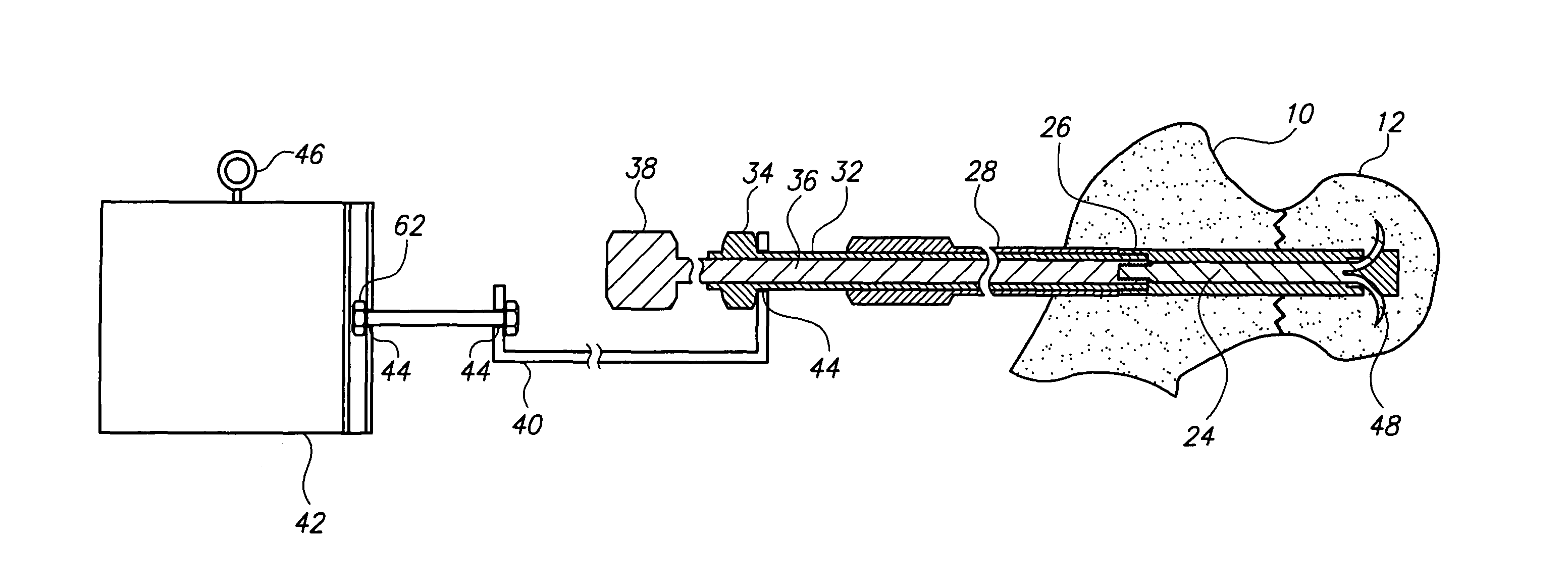
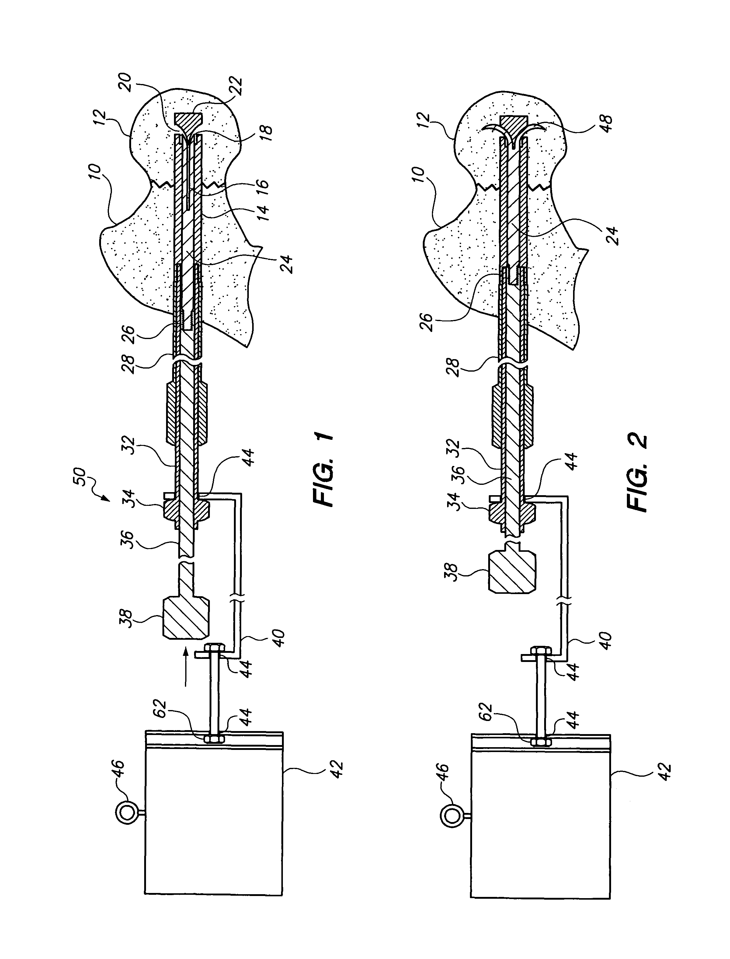
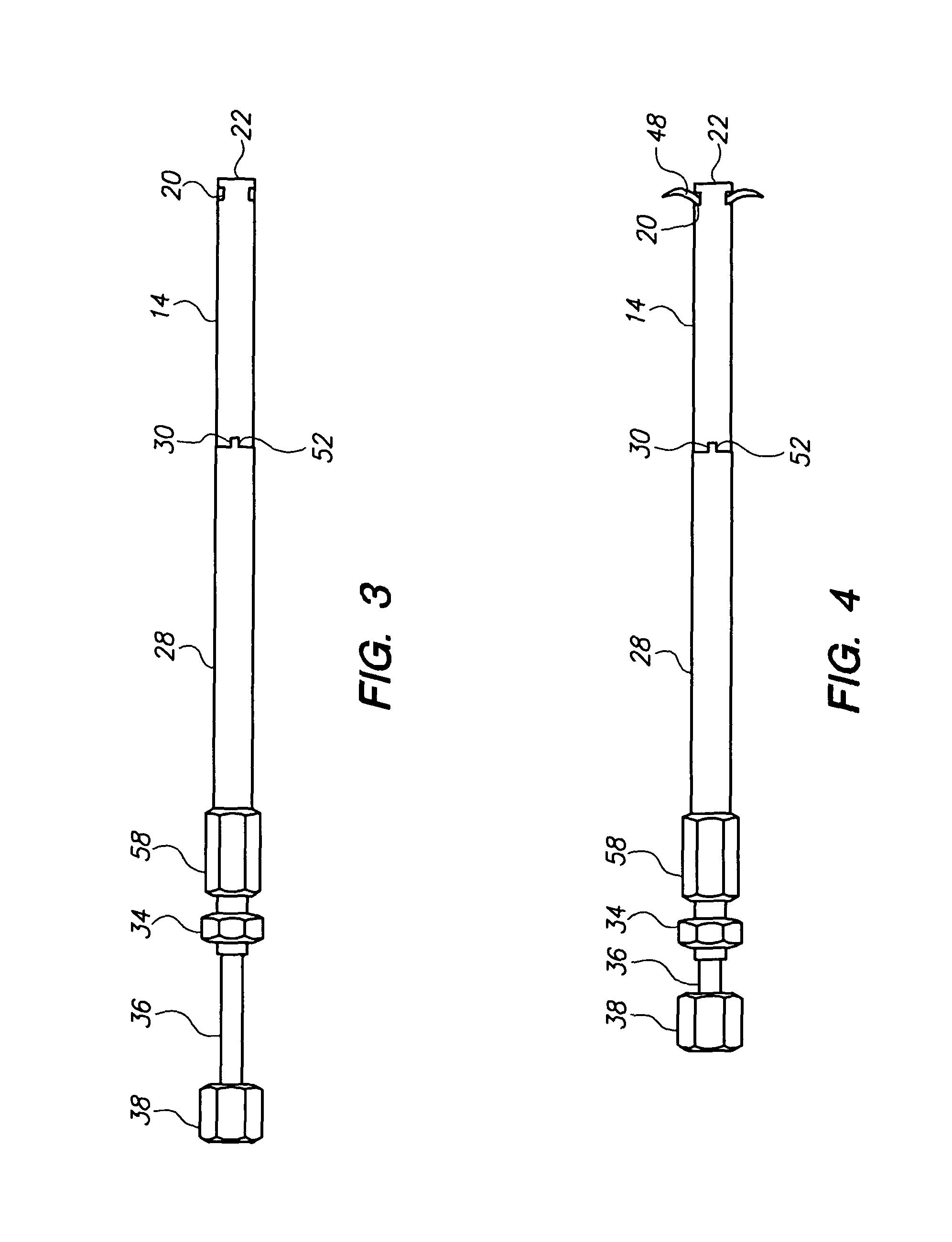
[0023]FIG. 1 is a sectional view showing the complete hip nail and insertion tooling assembly. The tubular nail sheath 14 with the tip of the nail 22 is embedded in the femoral head 12 across the fracture 10.

[0024]The tang bearing rod 24, is shown within the nail sheath 14, with the un-deployed locking tangs 16 with their tips 22 positioned in the openings with sloping floors 20. The locking tangs in one embodiment, are formed from the leading end of the tang bearing rod, and in another embodiment are formed separately and welded to the end of the rod, depending on the requirements of the tangs, such as their malleability and stiffness.

[0025]The angle of the slope of the floors of the openings 20 determines the angle of the segments, relative to the longitudinal axis of the nail after they have been extruded, which in one embodiment is approximately ninety degrees.

[0026]The trailing end of the tang bearing rod 24 is threaded for a coupling 26 with...


PUM


Abstract

A hip nail is inserted across a fracture of the proximal femur and locked in place by a plurality of tangs that are forcibly deployed from within the leading end of the nail into the head of the femur by means of blows on a central driving shaft, while a recoil transferring tube and tool shaft, and the inertia of a mass releasably attached to the base of the nail absorbs the recoil, enabling the nail to remain stationary relative to the bone, thereby enabling the tangs to deploy in a generally curvilinear perpendicular direction without twisting or unwanted distortion.

Description

FIELD OF THE INVENTION[0001]This invention generally relates to the combination of a surgical apparatus for rigidly inter-connecting fractured bones of the extremities, in particular, the proximal femur, together with a method and tooling for its insertionBACKGROUND OF THE INVENTION[0002]Compression screw systems are widely used to treat fractures of the proximal femur, including those of the femoral neck and the peri-trochanteric areas of the bone.[0003]The systems generally consist of a lag screw inserted from the lateral side of the femur, across the fracture and into the head of the femur, holding the bone fragments together. The trailing end of the screw may be supported either by a cortical side plate with a tubular barrel through which the nail can slide, or by an intramedullary nail with a transverse opening, that has been inserted longitudinally into the medullary canal of the femur.[0004]Their wide usage is based on their ability to compress the bone ends together to promo...

Claims


Application Information

Patent Timeline
IPC IPC(8): A61F2/46
CPCA61B17/742A61B17/8872A61B17/8894A61B2017/922
Inventor POWLAN, ROY Y.
Owner POWLAN ROY Y
Why Eureka
Try Eureka