Zoom lens and electronic still camera using it

a technology of electronic still camera and zoom lens, which is applied in the field of zoom lens and electronic still camera, can solve the problems of short overall optical length, inability to make high resolution overall images, and long overall optical length of the second lens group, and achieves short overall optical length and high resolution. , the effect of high resolution

Inactive Publication Date: 2005-08-02
PANASONIC CORP
View PDF31 Cites 17 Cited by
  • Summary
  • Abstract
  • Description
  • Claims
  • Application Information

AI Technical Summary

Benefits of technology

[0014]The present invention was arrived at in order to solve the foregoing problems of the prior art, and it is an object thereof to provide zoom lenses with a zoom ratio of ×2.5 to ×3.2 and an angle of view at the wide-angle end of about 60°, and that have high resolution and a short overall optical length when not in use, and moreover to provide zoom lenses that include a camera shake correction function. It is a further object of the present invention to use these zoom lenses to provide electronic still cameras with high resolution and that are thin in the depth direction when not being used, and furthermore to provide electronic still cameras that include a camera shake correction function.

Problems solved by technology

However, the astigmatism of the zoom lens disclosed in the aforementioned JP H11-287953A is insufficient for correcting the curvature of field, and thus there is the problem that the overall image cannot be made high resolution.
However, with the zoom lens disclosed in the aforementioned JP H11-52246A, since the second lens group includes a long air gap or a lens with a thick center portion, there is the problem that the overall length of the second lens group is long and even if a collapsing configuration is adopted, the overall optical length when collapsed is not very short.
Also, a moving lens barrel that moves during zooming and a stationary lens barrel that supports the moving lens barrel are required for a collapsing configuration, however, if the overall optical length during use is significantly longer than the overall optical length when collapsed, then the stationary lens barrel cannot stably support the moving lens barrel, and thus there is the problem that a portion of the lens groups becomes decentered, leading to a drop in the image-formation properties of the captured image.
The zoom lens disclosed in JP H11-52245A is made of ten or eleven lenses, and since the number of lenses is large, there is the problem of increased costs.
Another problem with the zoom lens disclosed in this publication is that it has poor telecentricity.
Because the number of pixels of solid-state imaging elements used in electronic still cameras is much larger than the number of pixels of solid-state imaging elements used in conventional video cameras, when a video camera zoom lens provided with a camera shake-correction function is used in an electronic still camera, the image-formation properties at the peripheral portion of image in a state where camera shake is corrected are poorer than the image-formation properties in a state where camera shake has not been corrected (in the standard state).
To do this, however, a large number of lenses must be combined, making the lens group that is parallel displaced heavy.
However, when the actuator is large, it is difficult to achieve an electronic still camera that is compact.

Method used


Image

  • Zoom lens and electronic still camera using it
  • Zoom lens and electronic still camera using it
  • Zoom lens and electronic still camera using it

Examples


first embodiment

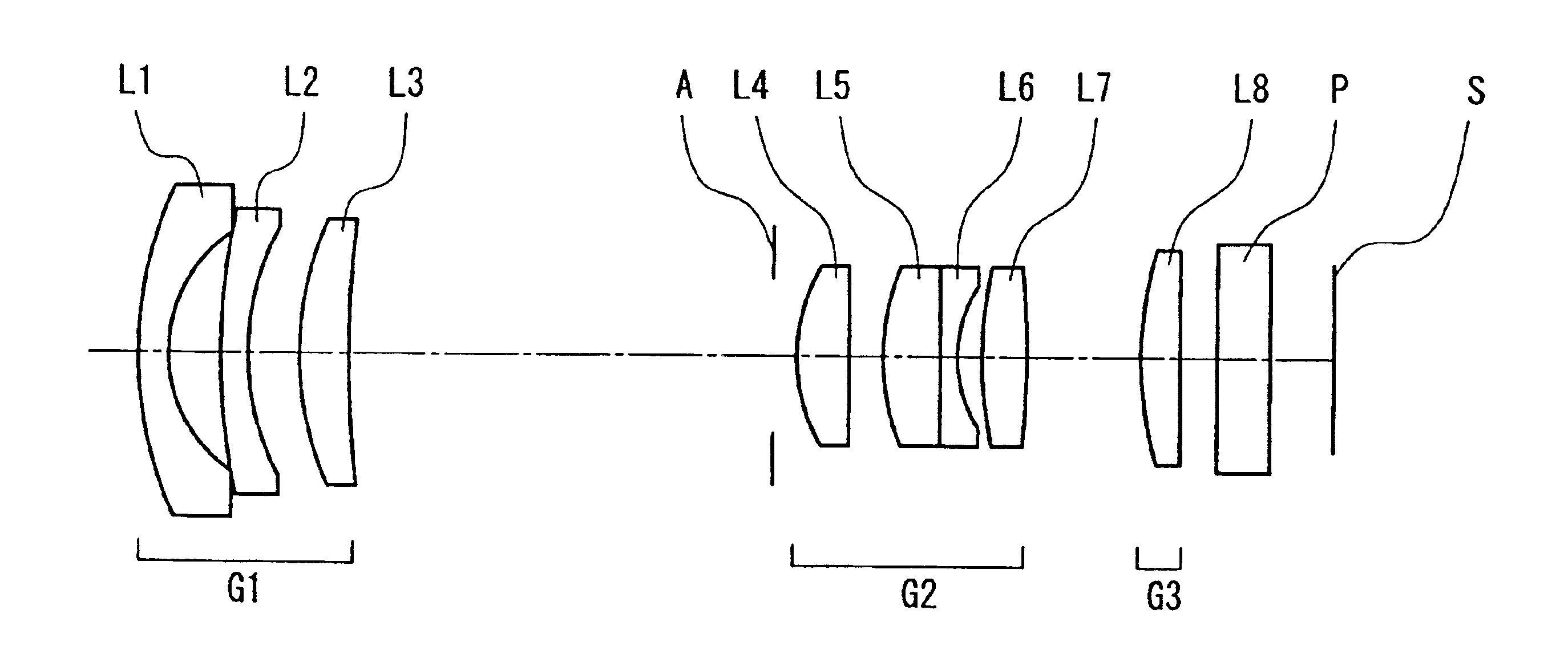
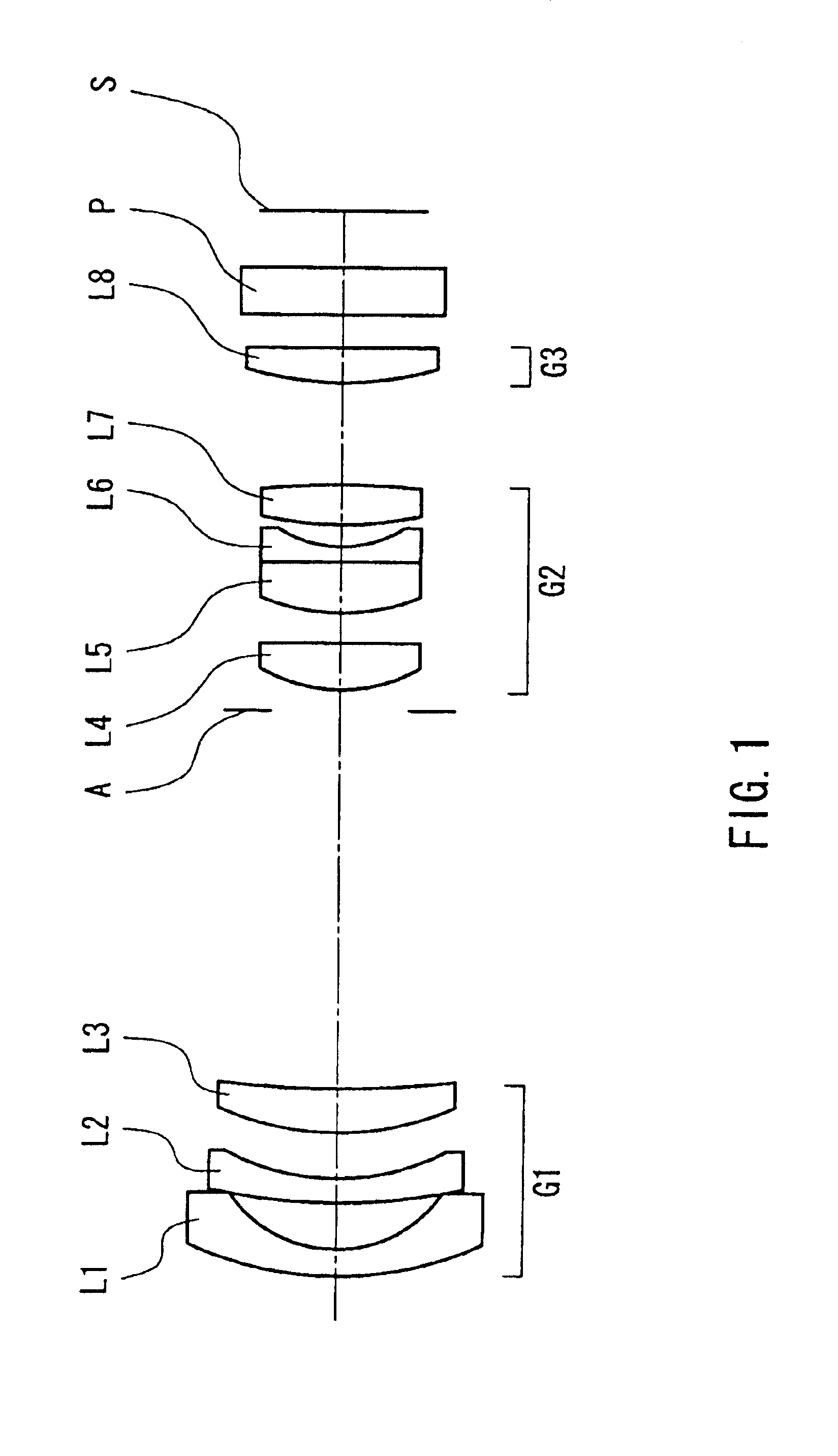
[0161]FIG. 1 is a layout drawing showing the configuration of a zoom lens according to a first embodiment of the present invention.

[0162]As shown in FIG. 1, the zoom lens of this embodiment is made of a first lens group G1 having a negative power, an aperture stop A, a second lens group G2 having a positive power, and a third lens group G3 having a positive power, arranged in that order from the object side (left side in FIG. 1) toward the image plane S side (right side in FIG. 1), and includes eight lenses.

[0163]The first lens group G1 is made of a first lens L1 that is a negative meniscus lens whose surface with strong curvature is facing the image plane S, a second lens L2 that is a negative meniscus lens whose surface with strong curvature is facing the image plane S, and a third lens L3 that is a positive lens whose surface with strong curvature is facing the object, arranged in that order from the object side.

[0164]The second lens group G2 is made of a fourth lens L4 that is a...

second embodiment

[0196]FIG. 6 is a layout drawing showing the configuration of a zoom lens according to the second embodiment of the present invention.

[0197]As shown in FIG. 6, the zoom lens of this embodiment is made of a first lens group G1 having a negative power, an aperture stop A, a second lens group G2 having a positive power, and a third lens group G3 having a positive power, arranged in that order from the object side (left side in FIG. 6) toward the image plane S side (right side in FIG. 6), and includes eight lenses.

[0198]The zoom lens shown in FIG. 6 has the same configuration as the zoom lens detailed above in the first embodiment (see FIG. 1), and is different only in the manner in which the seventh lens L7 is provided with an aspherical surface. That is, in the zoom lens shown in FIG. 1, the surface, whereas of the seventh lens L7 that is on the object side is an aspherical surface, whereas in the zoom lens according to this embodiment and shown in FIG. 6, the surface of the seventh l...

third embodiment

[0211]FIG. 11 is a layout drawing showing the configuration of a zoom lens according to a third embodiment of the present invention.

[0212]The zoom lens shown in FIG. 11 has the same configuration as the zoom lens detailed above in the second embodiment (see FIG. 6), and is different only in the manner in which the first lens group G1 is provided with aspherical surfaces. That is, in the first lens group G1 of the zoom lens shown in FIG. 6, the surface of the second lens L2 on the image plane S side is an aspherical surface, whereas in the first lens group G1 of the zoom lens according to this embodiment and shown in FIG. 11, the surface of the first lens L1 on the image plane S side is an aspherical surface. More specifically, the surface of the second lens L2 on the image plane S side is an aspherical surface whose local radius of curvature monotonically increases within the range from its center to the effective diameter.

[0213]It is preferable that the various conditions set forth...


PUM


Abstract

A zoom lens comprising, disposed in order from an object side to an image surface side, a negative-power first lens group, a diaphragm, a positive-power second lens group, and a positive power third lens group, characterized in that, when zooming from a wide-angle end to a telelscope end, an air gap between the first lens group and the second lens group shrinks and an air gap between the second lens group and the third lens group expands, the third lens group is movable in an optical axis direction for focusing, and a zoom ratio at a shooting distance of ∞ is 2.5- to 3.2-magnification.

Description

TECHNICAL FIELD[0001]The present invention relates to zoom lenses and electronic still cameras using the same. More specifically, it relates to high-picture quality zoom lenses used in electronic still cameras, zoom lenses provided with a camera shake-correction function, and electronic still cameras using these zoom lenses.BACKGROUND ART[0002]As personal computers have become more sophisticated and widespread, electronic still cameras quickly have gained popularity as image input devices. The total pixel number of the solid-state imaging elements used in electronic still cameras has reached more than 1 million pixels, and recently, electronic still cameras provided with solid-state imaging elements having a total pixel number greater than 3 million pixels also have appeared on the market. Video cameras that are capable of shooting high-quality still images in addition to moving pictures also have been released on the market.[0003]Although electronic still cameras come in many forms...

Claims


Application Information

Patent Timeline
Patent Type & Authority Patents(United States)
IPC IPC(8): G02B15/177G02B13/18
CPCG02B15/177G02B15/143507
Inventor MIYATAKE, YOSHITO
Owner PANASONIC CORP
Why Eureka
Try Eureka