Rotating shaft with radial press device

a technology of radial press and rotating shaft, which is applied in the direction of wing accessories, details of portable computers, instruments, etc., can solve the problems of prior art becoming loose, rotating shaft has to keep in a state of being unloosened, and it is not possible for prior art to provide the function

Inactive Publication Date: 2005-08-16
JARLLYTEC CO LTD
View PDF12 Cites 45 Cited by
  • Summary
  • Abstract
  • Description
  • Claims
  • Application Information

AI Technical Summary

Problems solved by technology

In fact, an excellent rotating shaft has to keep in a state of being unloosened in addition to an effect of standstill.
However, the prior art will become loose due to the wear-out at the contact area between the cylindrical rod and the axial hole after using a period of time.
Even more, it is not possible for the prior art to provide the function of automatic locking or the function of the anti-bounce.

Method used


Image

  • Rotating shaft with radial press device
  • Rotating shaft with radial press device
  • Rotating shaft with radial press device

Examples


Embodiment Construction

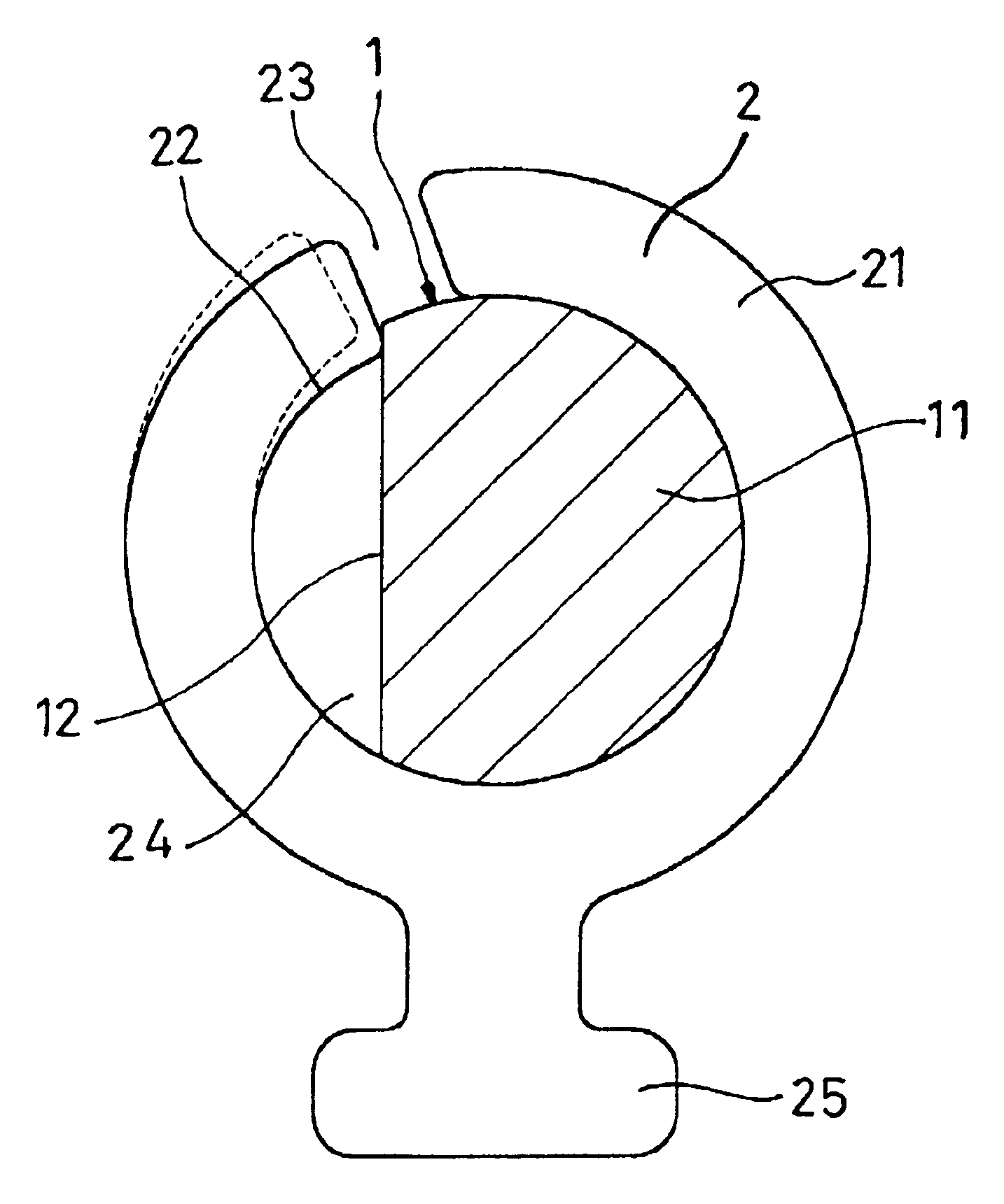
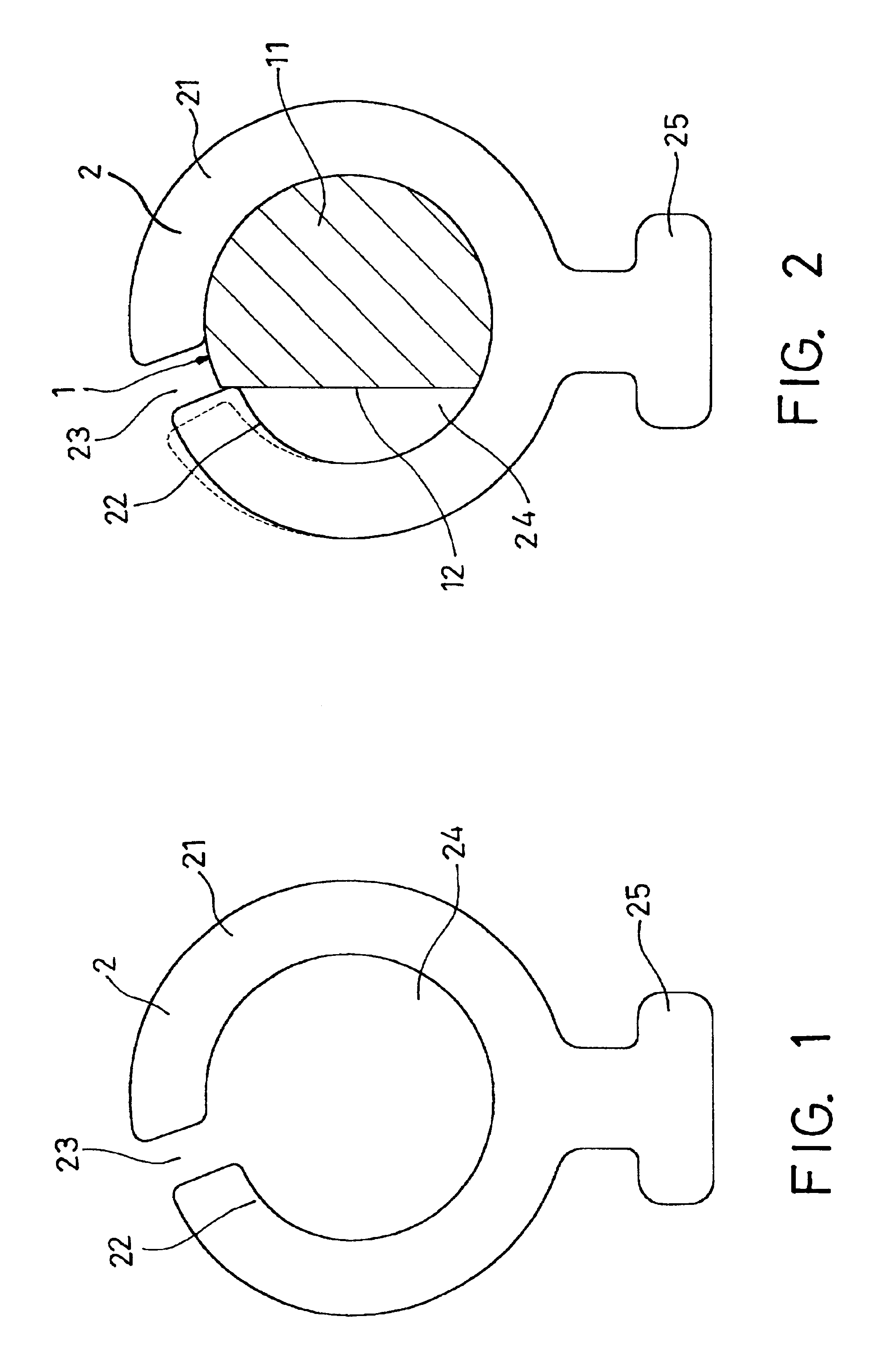
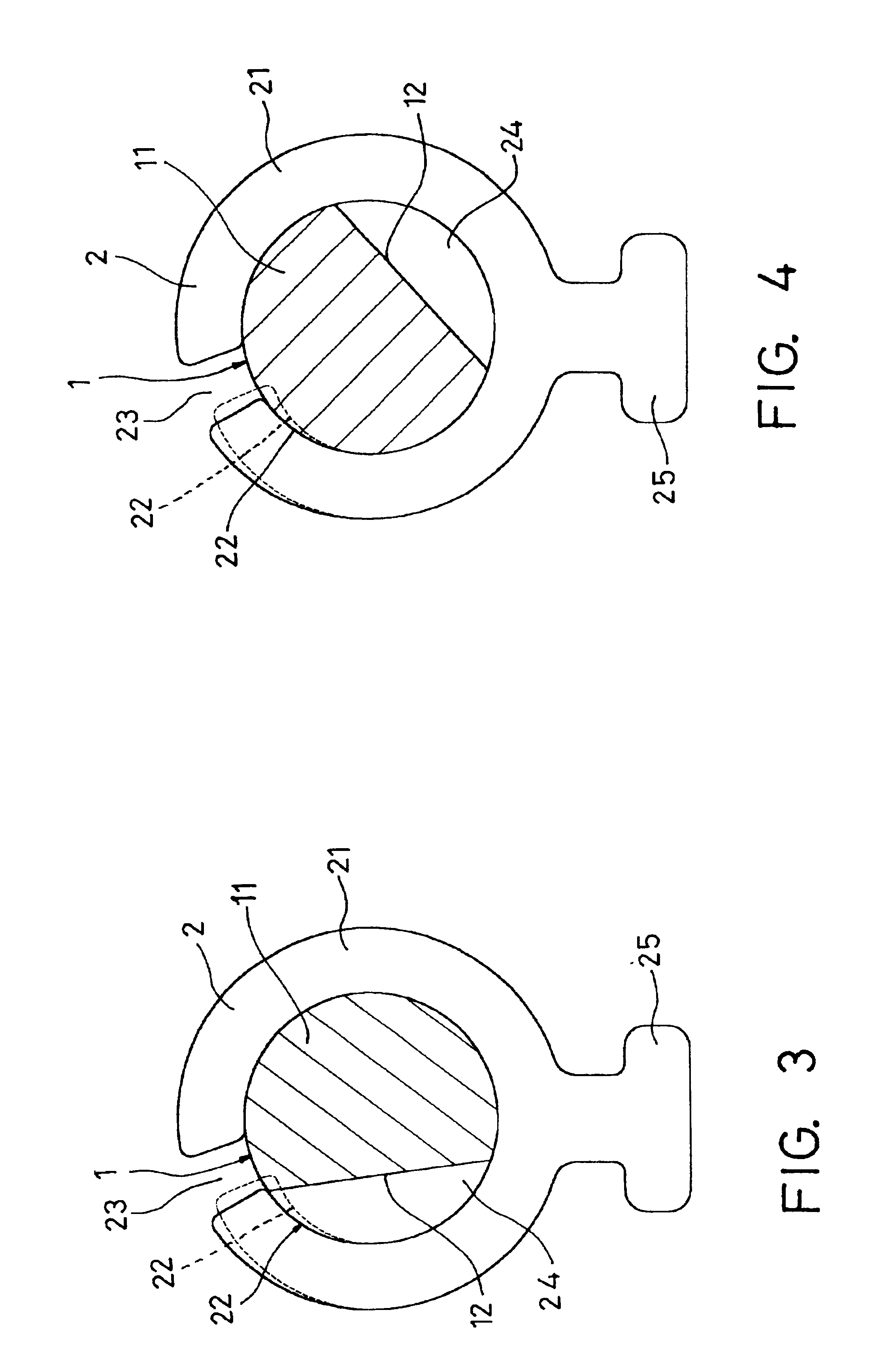
[0012]Referring to FIGS. 1 to 4, a rotating shaft with a radial press device according to the present invention comprises a shaft part 1 and at least a friction part 2.

[0013]Wherein, the shaft part 1 (it is known and not shown) at an end thereof connects with an article such as a screen and at another end thereof transversely extends a cylindrical rod 11 for being inserted into an axial hole 24 of the friction part 2 and forming a circumferential contact. The difference of the cylindrical rod 11 from the conventional ones is in that at least a milled face 12 at the periphery thereof is provided.

[0014]The friction part 2 can be flat or cylindrical and connects with another article such as a main unit. The friction part 2 is composed of a circular section 21 and an arched section 22 with a gradually reduced radius and a gap 23 is between the circular section 21 and the arched section 22. Both of the circular section 21 and the arched section 22 surround the axial hole 24 so that the a...


PUM


Abstract

A rotating shaft with radial press device comprises a cylindrical rod and at least a friction part. The cylindrical rod extends from the rotating shaft and provides at least a milled face. The friction part is a ring piece composed of a circular section and an arched section and a gap is formed between the circular section and the arched section. An axial hole is surrounded by both of the circular section and the arched section for accommodating the cylindrical rod. Further, the arched section has a gradually reduced inner radius. As soon as the cylindrical rod is tightly pressed by the arched section, a position of standstill can be formed and when the milled face touches the free end of the arched section, the cylindrical rod can moves in a direction so that the milled face keeps contact with the free end of the arched section in a state of locking automatically.

Description

BACKGROUND OF THE INVENTION[0001]1. Field of the Invention[0002]The present invention relates to a rotating shaft with radial press device, and, particularly to a rotating shaft, which provides a function of automatic locking or a function of anti-bounce.[0003]2. Description of Related Art[0004]A consumptive electronic product with lifted lid such as a portable computer, an electronic dictionary, . . . , and so on mostly has a lower main unit to pivotally connect with an upper lifted lid by way of a rotating shaft so that the lid can be opened and shut relative to the main unit. Hence, the rotating shaft is an important element to determine if the consumptive electronic product is good or bad. In fact, an excellent rotating shaft has to keep in a state of being unloosened in addition to an effect of standstill.[0005]Generally, the friction generated from the rotating shaft can be classified into two categories, the series connection mode and the fitting mode. The series mode is so-c...

Claims


Application Information

Patent Timeline
Patent Type & Authority Patents(United States)
IPC IPC(8): E05D11/00E05D11/10E05D11/08G06F1/16E05D11/06
CPCG06F1/1679G06F1/1681G06F1/1616E05D11/06E05D11/082E05D11/084E05D11/1007E05D11/1014E05Y2900/606Y10T16/54038Y10T16/557Y10T16/54035Y10T16/54033
Inventor HUONG, CHIN-FU
Owner JARLLYTEC CO LTD
Why Eureka
Try Eureka