Quick exchange infinity mirror display apparatus and method

a technology of infinity mirror and display case, which is applied in the field of devices for creating infinity mirror display effects, can solve the problems of limited use of prior art devices for display of collectibles and other items, inability to easily exchange for one another, and limited ease in creating new visual effects, so as to achieve rapid and easy addition and removal, and rapid and easy access to its interior space

Inactive Publication Date: 2005-08-16
HARGABUS PATRICK ALLEN
View PDF8 Cites 23 Cited by
  • Summary
  • Abstract
  • Description
  • Claims
  • Application Information

AI Technical Summary

Benefits of technology

[0006]The primary object of this invention is to provide an infinity mirror display apparatus configured for displaying multiple spaced-apart reflections extending rearwardly and perhaps also laterally from one or more illuminated display objects positioned in the interior space defined between a stationary base member and a removable cover, and which is adapted to permit nearly instantaneous access to the interior space so that three-dimensional display objects can be quickly and easily added and removed therefrom. It is also an object of this invention to provide an infinity mirror display apparatus that can remain in its mounted position during display object exchange or addition. A further object of this invention is to provide an infinity mirror display apparatus that includes multi-sided covers. It is also an object of this invention to provide an infinity mirror display apparatus in which the dis

Problems solved by technology

One disadvantage of prior art infinity display devices is that once a three-dimensional display object is placed in its operative position relative to the mirrors, it is not easily exchanged for another.
This limits the use of prior art devices for di

Method used


Image

  • Quick exchange infinity mirror display apparatus and method
  • Quick exchange infinity mirror display apparatus and method
  • Quick exchange infinity mirror display apparatus and method

Examples


embodiment 2

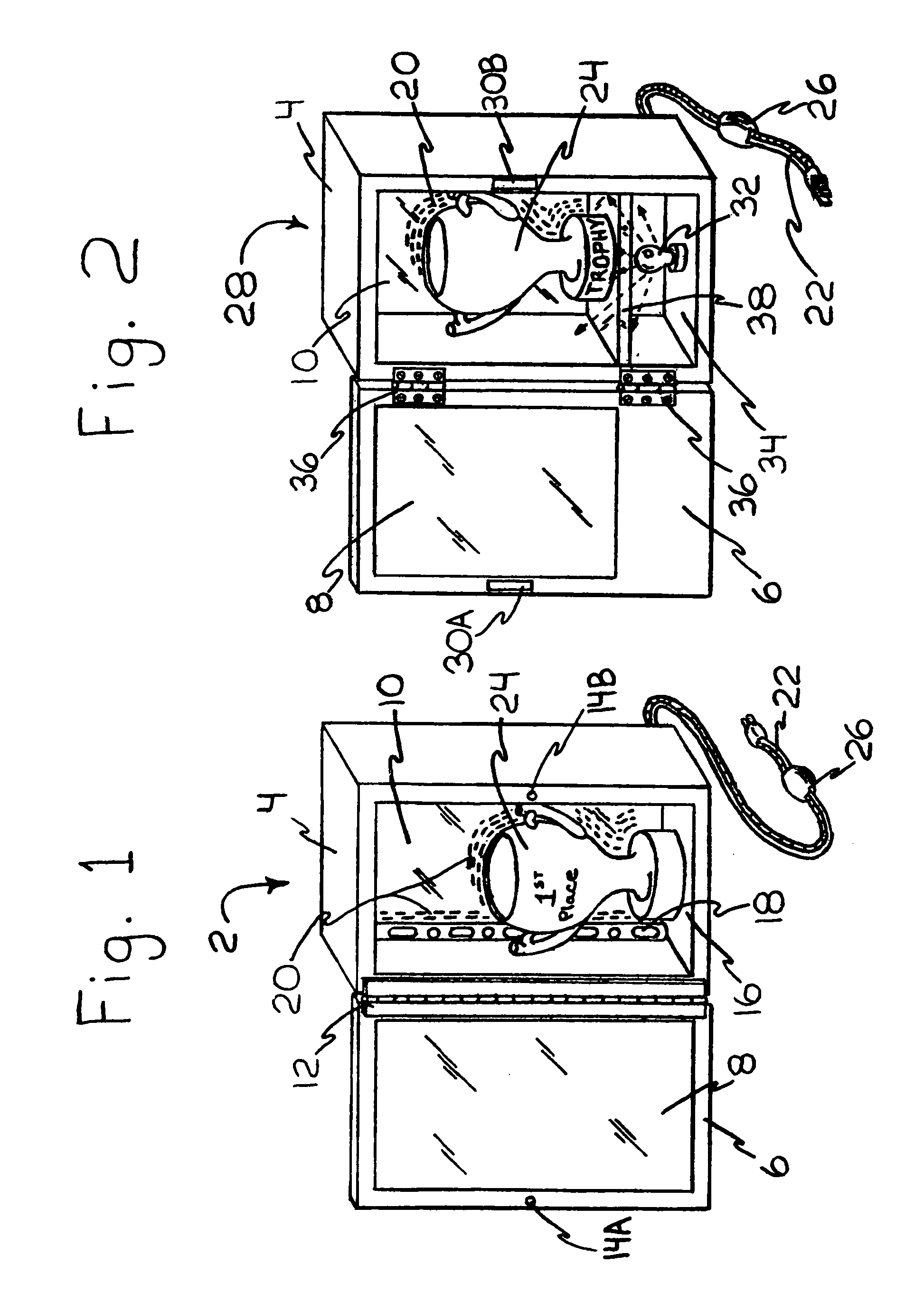
[0023]FIG. 1 also shows a two-part fastener consisting of first fastener 14a and second fastener 14b being use to achieve secure closure of cover 6 against stationary base member 4 when cover 6 is in its fully closed position. The type of fastening means used for first fastener 14a and second fastener 14b is not critical and any type or number of secure but easily opened closure means, such as a snap-fit type of closure, as well as locking closure means between the stationary base member 4 and cover 6, such a keyed fastener 44 in FIG. 3, are considered to be within the scope of the present invention as long as all are easily manipulated for prompt access to the interior space defined between stationary base member 4 and cover 6. A handle could optionally be positioned on the reverse side of cover 6 not visible in FIG. 1, anywhere along the distal edge of the frame of cover 6 in a position remote from hinge 12. However, generally a handle is not preferred and instead cover 6 can be m...

embodiment 90

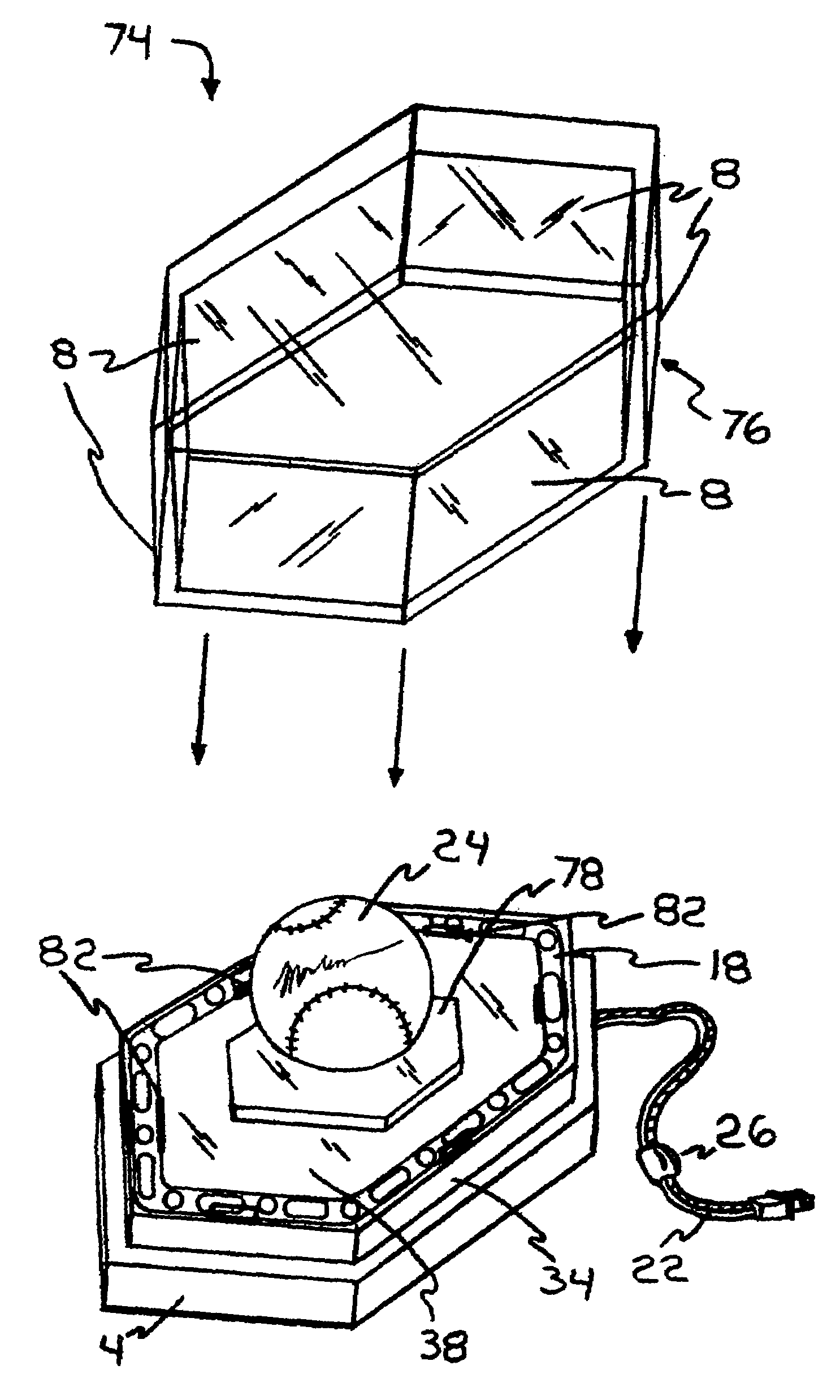
[0031]FIG. 11 shows a tenth preferred embodiment 90 of the present invention having a rectangular housing with a totally reflective rear surface 10 and a front surface having a partially reflective surface 8, and two sides each having a partially reflective surface 8′, as well as a light source 32 attached through the top end of stationary base member 4, which also serves as cover 6 and can be vertically lifted away from stationary base member 4, as shown by the upwardly directed arrow adjacent to the front left corner of cover 6, so as to give access to the interior space defined by stationary base member 4 and cover 6 for the exchange of display objects 24 Although cover 6 is shown as opaque, it could alternatively comprise a partially reflective surface 8. Also, totally reflective rear surface 10 could be replaced by a partially reflective surface 8. The number, relative positioning through the top end of stationary base member 4, type of lighting used, and configuration of light...


PUM


Abstract

An infinity mirror display apparatus, and method of manufacture, which allows private and commercial users to rapidly trade out favored display objects to create different infinity display effects for continued viewer interest and enjoyment. The apparatus comprises a housing having a stationary base member and an easily removable cover which together define an enclosed interior space, at least two reflective surfaces positioned adjacent to the interior space with at least one of the surfaces being partially reflective, and at least one illumination source communicating with the interior space. The cover can be partially or totally removed from the stationary member during display object exchange. The apparatus can be wall-mounted for front and/or side viewing of the infinity mirror effect, or it can be table-mounted with multiple partially reflective surfaces for a full 360° view of the infinity mirror effect created by one or more illuminated display objects.

Description

CROSS REFERENCES TO RELATED PATENT APPLICATIONS[0001]This is a continuation-in-part utility patent application based upon the invention disclosed in U.S. patent application Ser. No. 09 / 677,705 to the same inventor, filed Sep. 30, 2000, and has been allowed to issue as U.S. Pat. No. 6,709,339, which is a continuation-in-part utility patent application based upon the invention disclosed in U.S. patent application Ser. No. 09 / 375,894 to the same inventor, filed Aug. 17, 1999, now abandoned, and benefit of the previous co-pending patent applications is requested herein.BACKGROUND[0002]1. Field of Invention[0003]This invention relates to devices for creating infinity mirror display effects, specifically to an openable infinity mirror display case or apparatus, and a method for its manufacture, which has a base member that remains stationary during use, an easily removable cover that is placed during use in a closed position against the base member to define an interior space, an illumina...

Claims


Application Information

Patent Timeline
IPC IPC(8): G09F19/12G09F19/16
CPCG09F19/16
Inventor HARGABUS, PATRICK ALLEN
Owner HARGABUS PATRICK ALLEN
Why Eureka
Try Eureka