
Method and system of universal RFID communication

a technology of universal rfid and base unit, applied in the field of rfid, can solve the problems of unnecessary further discussion of their modes of operation, dumb terminals of rfid readers designed to operate with central computers, and the rapid inundation of central computers with requests and responses, etc., and achieve the effect of quick and easy addition

Active Publication Date: 2011-11-22
INTELLECTUAL TECH LLC
View PDF23 Cites 5 Cited by
  • Summary
  • Abstract
  • Description
  • Claims
  • Application Information

AI Technical Summary

Benefits of technology

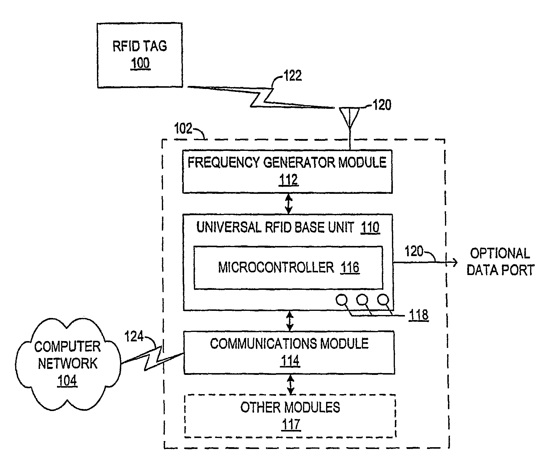
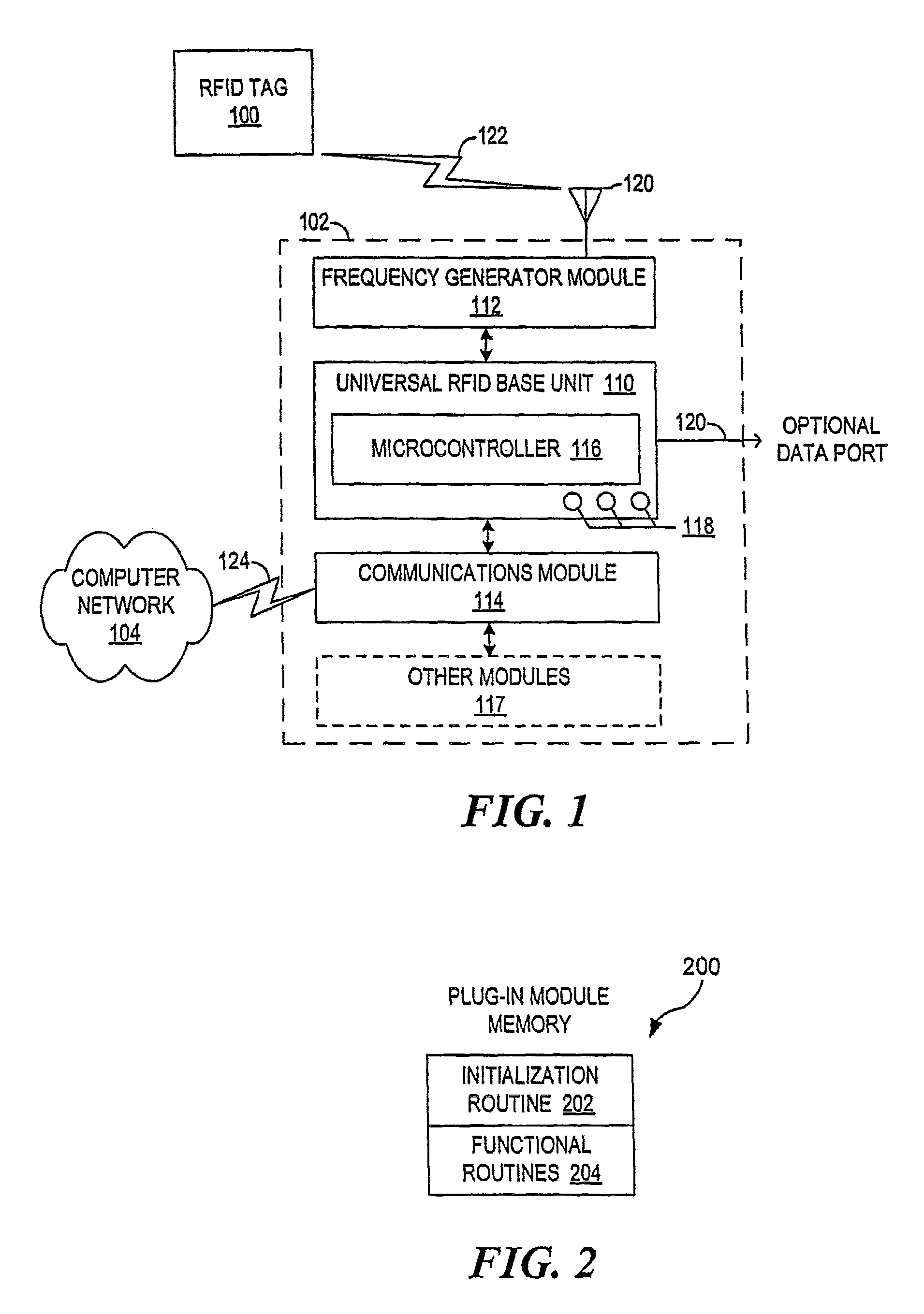
[0021]In another aspect, various other additional connector-compatible modules, such as industrial modules, can be quickly and easily added. In such an arrangement, the microcontroller may provide industrial control functions, such as, for example, operating a relay relative to a given set or combination of “read” operations.

Problems solved by technology

It is believed that since the operation of various types of tags is well known, further discussions of their modes of operation are unnecessary.
It should be noted that conventional RFID readers designed to operate with central computers are dumb terminals in that the readers read tags and send data only upon request from the central computer.
Thus the central computer may quickly be inundated with the number of requests and responses required in the process when operating with a large number of readers.
However, such systems have been expensive to set up and operate.

Method used


Image

  • Method and system of universal RFID communication
  • Method and system of universal RFID communication
  • Method and system of universal RFID communication

Examples


Embodiment Construction

[0027]In the following discussion, numerous specific details are set forth to provide a thorough understanding of the present invention. However, those skilled in the art will appreciate that the present invention may be practiced without such specific details. In other instances, well-known elements have been illustrated in schematic or block diagram form in order not to obscure the present invention in unnecessary detail. Additionally, for the most part, details concerning network communications, electro-magnetic signaling techniques, and the like, have been omitted inasmuch as such details are not considered necessary to obtain a complete understanding of the present invention, and are considered to be within the understanding of persons of ordinary skill in the relevant art.

[0028]It is further noted that, unless indicated otherwise, all functions described herein may be performed in either hardware or software, or some combinations thereof. In a preferred embodiment, however, th...


PUM


Abstract

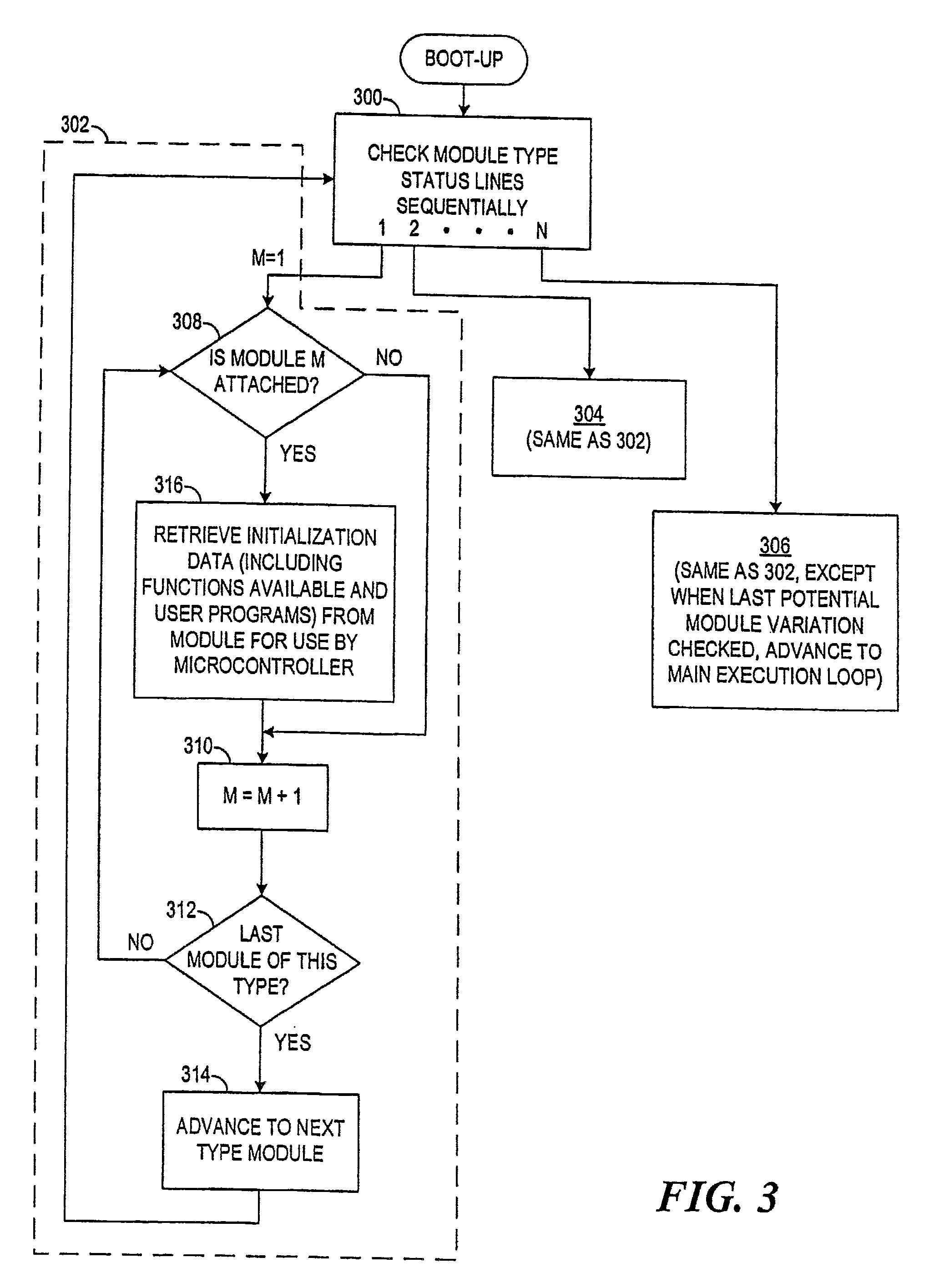
A method and an apparatus are provided for a universally operable Radio Frequency Identification (RFID) tag reader base unit. An RFID base unit is provided that can communicate with at least two different types of RFID tags, one at a time, that are commercially available as well as communicate with data collecting entities using any of at least two communication standards. The reader comprises a microprocessor (microcontroller) portion having at least one set of plug-in connectors. The reader then operates in different operational logic processes in accordance with the types and parameters of attached plug-in modules. The plug-in modules will typically comprise RF frequency modules for communicating with the RFID tags as well as a communication standard model for communicating with a computer network. Additionally, the plug-in modules contain memory that contains data and code used by the microprocessor in performing the operations obtainable by specific types of plug-in modules. If upgrading of the operating system is required, such upgrading can be accomplished through the use of an associated port such as a microcontroller interface port, a memory stick slot or using a computer in conjunction with a communication module.

Description

CROSS-REFERENCE TO RELATED APPLICATIONS[0001]This application is a continuation of prior application Ser. No. 11 / 064,869, filed Feb. 24, 2005.[0002]The entire contents of U.S. Pat. No. 7,233,247, entitled: “METHOD AND SYSTEM FOR EMPLOYING RFID TAGS IN AUTOMATED APPLICATIONS” issued on 19 Jun. 2007, are incorporated herein by reference for all purposes.FIELD OF THE INVENTION[0003]The present invention relates generally to Radio Frequency Identification (RFID) and, more particularly, to an RFID base unit reader that may be easily, quickly and economically converted to read tags of different types and / or using different protocols and provide outgoing data in various communication standard formats.DESCRIPTION OF THE RELATED ART[0004]RFID tags and tag reader devices have been around since World War II. The first known usage of RFID tags was by the United Kingdom's Royal Air Force. The RAF placed RFID tags in their aircraft, so that the Spitfires and other allied aircraft could be disting...

Claims


Application Information

Patent Timeline
Patent Type & Authority Patents(United States)
IPC IPC(8): G06K7/00G08B13/14H04Q5/22G06K7/08G06K19/00
CPCG06K7/0008G08B13/2402H04Q2213/13095
Inventor CROSSNO, ADAMKEY, DENNIS SHAWNPUTTAGUNTA, VISWANATHVISWARAJU, RAVI KUMAR
Owner INTELLECTUAL TECH LLC
Learn More