Lancing device

Inactive Publication Date: 2005-08-16
ARKRAY INC
View PDF9 Cites 157 Cited by
  • Summary
  • Abstract
  • Description
  • Claims
  • Application Information

AI Technical Summary

Benefits of technology

[0008]An object of the present invention is to provide a lancing

Problems solved by technology

However, the prior art device has the following problems.
Thus, with the prior art device, sticking of the lancet L into the skin just by an intended amount is difficult.
As a result, due to excess or

Method used


Image

  • Lancing device
  • Lancing device
  • Lancing device

Examples


Embodiment Construction

[0040]Preferred embodiments of the present invention will be described below in detail with reference to the accompanying drawings.

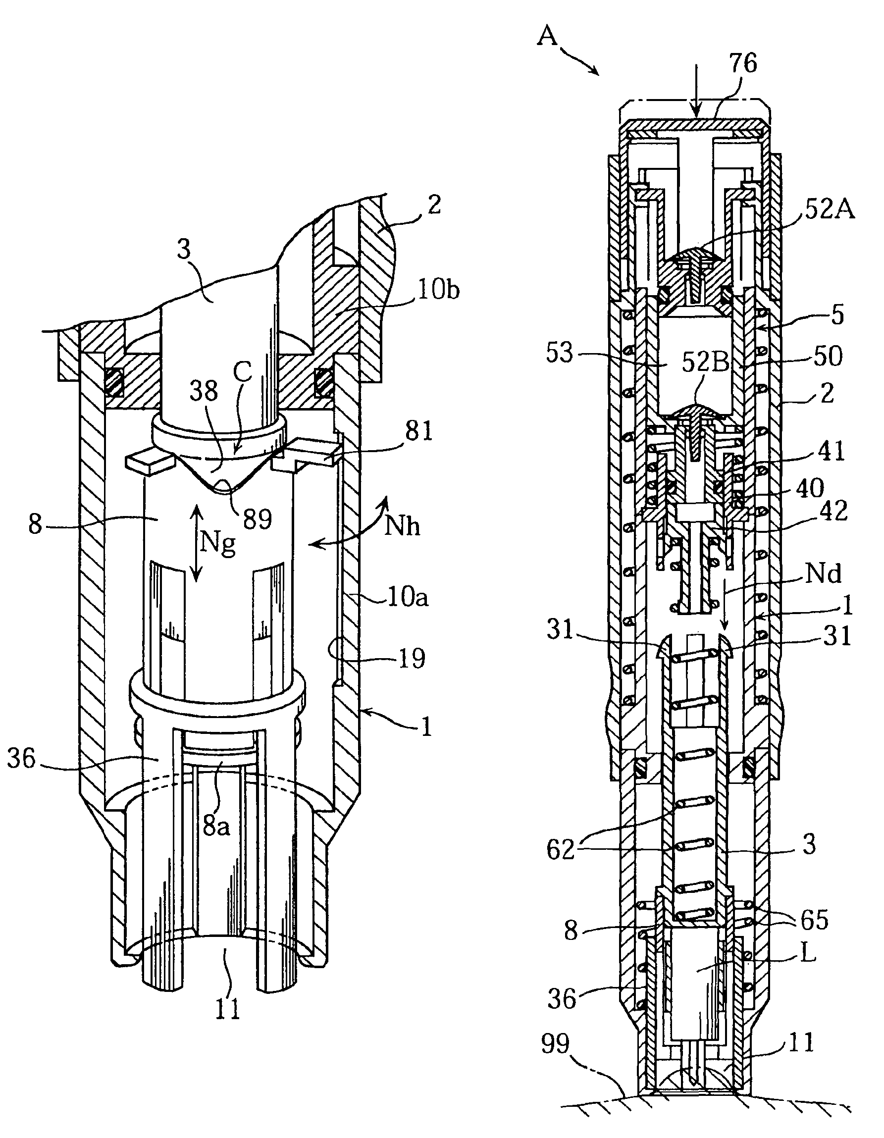
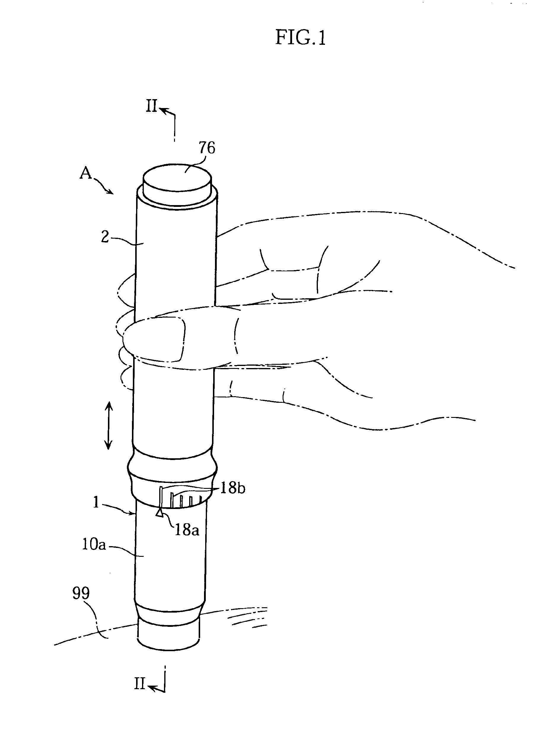
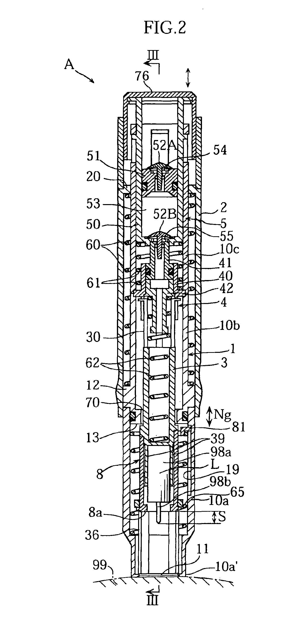
[0041]FIGS. 1-11 illustrate an example of a lancing device according to the present invention. As shown in FIG. 2, the lancing device A in this embodiment includes a housing 1, an outer cylinder 2, a lancet holder 3 for removably holding a lancet L, an auxiliary member 8 attached to the lancet holder 3, a latch mechanism 4 for the lancet holder 3, and a pump mechanism 5 defining a pressure chamber 53 for producing negative pressure. The lancet L comprises a generally columnar main body 98a formed of e.g. synthetic resin and a metal needle 98b projecting from the tip end surface of the main body. Preferably, for good hygiene, the lancet L is used only once and disposed after use.

[0042]The housing 1 comprises, for example, three sleeves 10a-10c connected to each other in series and has a generally cylindrical configuration having a tip end formed with an o...


PUM


Abstract

A lancing device (A) includes an auxiliary member (8) located on a side of the tip end portion of a lancet (L). By moving the auxiliary member (8), the dimension (s) of the tip end of the lancet (L) projecting from the tip end portion (8a) of the auxiliary member (8) can be varied. The variation of the dimension (S) makes it possible to stick the lancet (L) into the skin (99) of a user precisely by an intended amount.

Description

TECHNICAL FIELD[0001]The present invention relates to a lancing device used for sticking a tip end of a lancet into skin for taking blood or other body fluid or tissue for examination.BACKGROUND ART[0002]An example of prior art lancing device is disclosed in JP-A-11-9577. As shown in FIG. 16, the prior art device includes a generally cylindrical housing 90 and a lancet holder 92 arranged in the housing for holding a lancet L. A cylindrical plunger 93 is fitted into one end of the housing 90. In this prior art device, when the plunger 93 is pushed in the arrow N1 direction, the lancet holder 92, which has latched on a predetermined portion in the housing 90, is forced to be released from the latched state. As a result, the lancet holder 92 advances toward a tip end opening 90a of the housing 90 due to the resilient force of a spring 95. As shown in FIG. 16C, a tip end surface 90b of the housing 90 is pressed against skin 99, so that the advancing movement of the lancet holder 92 caus...

Claims


Application Information

Patent Timeline
IPC IPC(8): A61B5/15
CPCA61B5/1411A61B5/15186A61B5/150022A61B5/150099A61B5/15019A61B5/150412A61B5/150503A61B5/15113A61B5/15117A61B5/1519A61B5/15194A61B5/150183
Inventor FUKUZAWA, MASAHIROHIRAO, ETSUO
Owner ARKRAY INC
Why Eureka
Try Eureka