Cantilevered screw assembly

a technology of cantilever screw and assembly, which is applied in the direction of conveyor parts, transportation and packaging, packaging, etc., can solve the problems of increasing the system maintenance necessary, limiting the system productivity, and adding to the operational cost of the system, so as to reduce the weight and manufacturing complexity, increase the load-bearing capacity of the assembly, and increase the girth of the load-bearing wall

Active Publication Date: 2016-04-07
KOMAR IND LLC
View PDF0 Cites 1 Cited by
  • Summary
  • Abstract
  • Description
  • Claims
  • Application Information

AI Technical Summary

Benefits of technology

[0006]Needs also exist to reduce the weight and manufacturing complexity of cantilevered screw assemblies. Some known cantilevered screw assemblies simply increase the girth of a load-bearing wall or include a series of bracing members in an attempt to increase the assemblies' load-bearing capacity. The assemblies of some known cantilevered screw assemblies also require many separate parts to be welded or otherwise assembled together to create the cantilevered screw assembly. This requires additional design and manufacturing complexity, including time, material, equipment, and labor resources to manufacture the assembly. Further, the additional fasteners, weld material, and other assembly devices add more weight to the assembly.
[0007]Exemplary embodiments may satisfy one or more of the aforementioned needs. One exemplary embodiment of a cantilevered screw assembly may include at least one bearing that includes solid oil. For example, one embodiment of a cantilevered screw assembly may include at least one bearing that is filled with solid oil. Such embodiments of a cantilevered screw assembly may offer numerous advantages including substantially decreased maintenance, lower operational costs, higher system efficiency, and improved environmental characteristics. It is estimated that the bearings of some exemplary embodiments may last at least two times longer between maintenance intervals as compared to a comparable cantilevered screw assembly that uses grease-lubricated bearings, which may significantly lower operational costs and raise operational efficiency. Moreover, oil leaks and drips may be substantially eliminated, drastically reducing the environmental impact.
[0008]Another exemplary embodiment of a cantilevered screw assembly includes an improved anchor system comprising at least one load-bearing wall. In particular, an exemplary embodiment may comprise a screw that is cantilevered to at least one wall. Examples of the improved anchor system may allow for a larger screw without compromising stability or the integrity of the load-bearing wall. Also, exemplary embodiments may enable more material to be processed by the cantilevered screw assembly with greater power and torque. Exemplary embodiments may further allow for reduced construction costs and assembly size when compared to assemblies requiring additional walls or other large assemblies for cantilevering the screw assembly.
[0009]Another exemplary embodiment of a cantilevered screw assembly includes a bearing housing and a wall comprised of a single casting. In particular, the wall may be cast with at least a portion of the bearing housing in an exemplary embodiment. For example, the bearing housing may comprise a body, a flared edge, a plurality of flanges, and / or a number of receptacles that are formed of a single casting with the support wall, thereby eliminating the need to manufacture and assemble these parts separately. In an exemplary embodiment, the single casting may reduce manufacturing and assembly costs when compared to assemblies requiring that these parts be manufactured separately and assembled. This may additionally reduce excess material such as weld material, fasteners, other assembly devices, or other excess material otherwise required to manufacture the assembly, which may reduce the weight of the assembly. Further, this may eliminate or lessen the need for increased girth of the walls or additional bracing members. This may also allow for increased strength and rigidity of a comparable or lesser weight assembly.

Problems solved by technology

While effective, the reservoir of grease needs to be periodically refilled, which increases the necessary maintenance of the system.
The associated downtime also limits the productivity of the system.
In addition, replenishing the grease adds to the operational cost of the system.
A further drawback is that the grease will eventually lead to oil drips or other oily messes.
The screws of some known cantilevered screw assemblies have a tendency to shift in position or wobble during operation.
The anchoring of known cantilevered screw assemblies may also limit load-bearing capacity.
The load-bearing wall may limit the size of the screw and the amount of material that can be processed.
If the size of the screw is excessive, it may compromise the load-bearing wall.
For example, it may lead to oil canning of the load-bearing wall.
Oil canning may affect the operation of the screw as aforementioned, and it may eventually render the system inoperable.
This requires additional design and manufacturing complexity, including time, material, equipment, and labor resources to manufacture the assembly.
Further, the additional fasteners, weld material, and other assembly devices add more weight to the assembly.
It is estimated that the bearings of some exemplary embodiments may last at least two times longer between maintenance intervals as compared to a comparable cantilevered screw assembly that uses grease-lubricated bearings, which may significantly lower operational costs and raise operational efficiency.

Method used


Image

  • Cantilevered screw assembly
  • Cantilevered screw assembly
  • Cantilevered screw assembly

Examples


Embodiment Construction

)

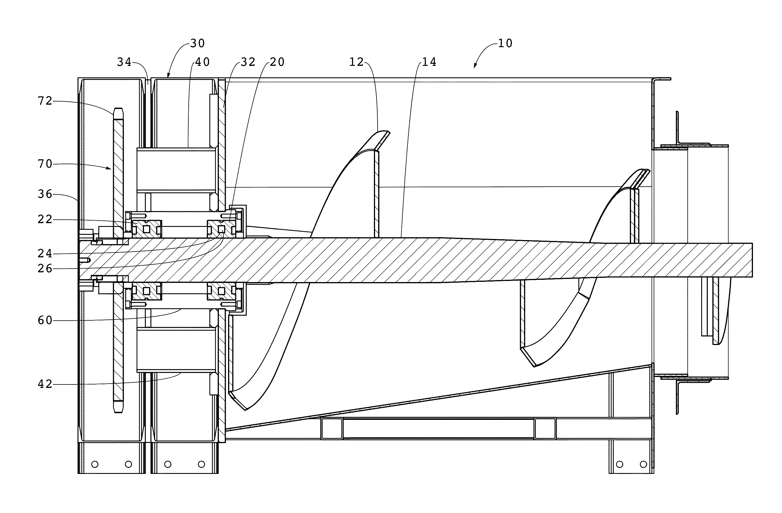
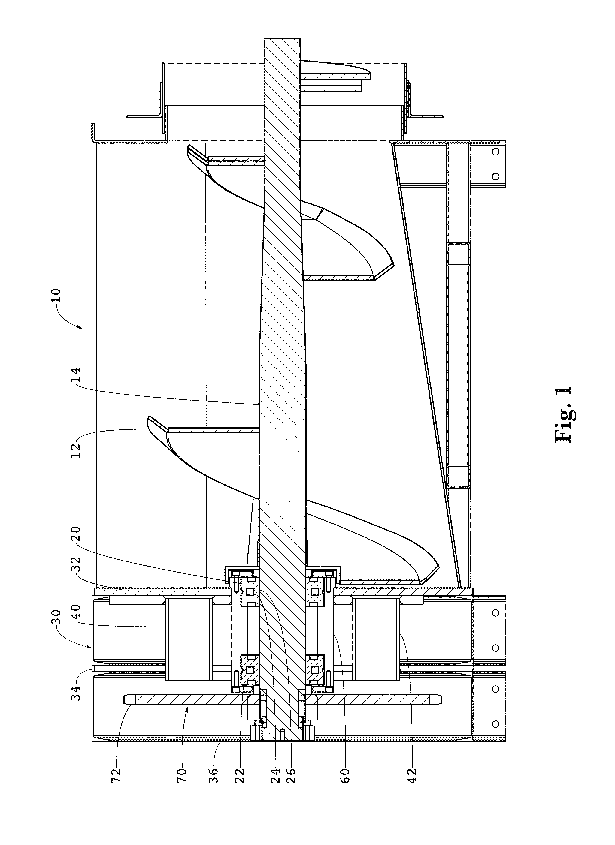
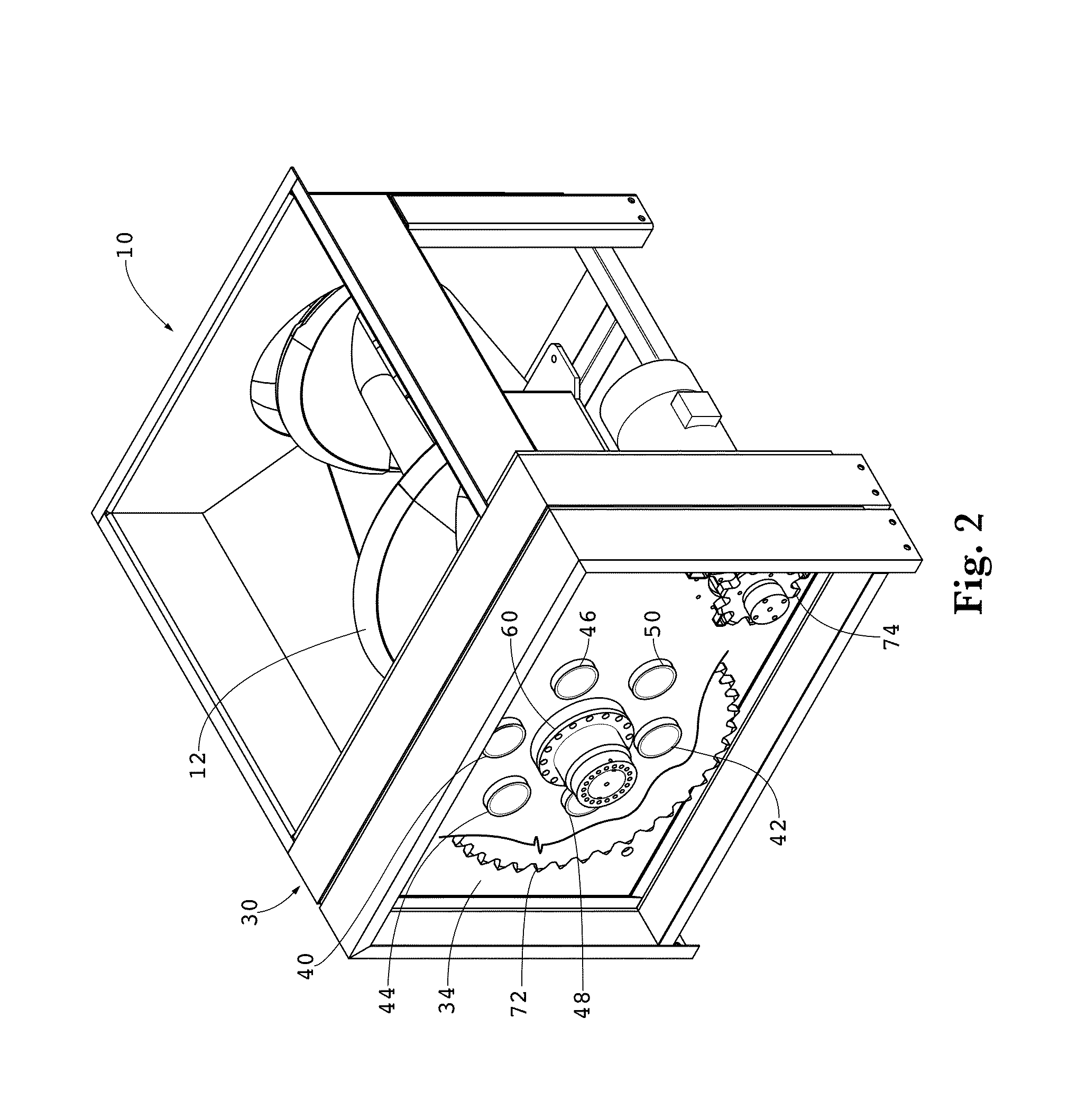
[0025]Exemplary embodiments of the present invention are directed to a cantilevered screw assembly. FIGS. 1-6 show various views of one embodiment of a cantilevered screw assembly 10 comprising a screw 12, which has a shaft 14. In this example, the shaft 14 has a slight taper. Other types of cantilevered screw assemblies may also benefit from aspects of the present invention. For instance, some embodiments may not have a shaft with a taper, while other embodiments may have a shaft with a reverse taper. For embodiments that have a shaft with a taper or reverse taper, the degree of the taper or reverse taper may be selected to fit the application of the cantilevered screw assembly.

[0026]One aspect of an exemplary embodiment is the use of at least one solid oil bearing in association with shaft 14 to facilitate rotation. In the example of FIG. 1, a first solid oil bearing 20 and a second solid oil bearing 22 enable rotation of shaft 14. Other exemplary embodiments may include the use ...


PUM


Abstract

A cantilevered screw assembly comprising an improved anchor system. In an exemplary embodiment, a support wall may be formed of a single casting with at least a portion of a bearing housing. An exemplary embodiment of a cantilevered screw assembly may also comprise at least one solid oil bearing to facilitate rotation of the screw.

Description

[0001]This application is a continuation-in-part of U.S. application No. 14 / 818,751, filed Aug. 5, 2015, which is a continuation of U.S. application No. 13 / 667,313, filed Nov. 2, 2012, which claims the benefit of U.S. Provisional Application No. 61 / 555,863, filed Nov. 4, 2011, each of which is incorporated by reference in its entirety.BACKGROUND AND SUMMARY OF THE INVENTION[0002]Exemplary embodiments of the present invention relate generally to a cantilevered screw assembly. Examples of cantilevered screw assemblies may include, but are not limited to, augers, compactors, crushers, shredders, feeders, material handlers, bale breakers, briquetters, and autoclave sterilizers. Other applications of cantilevered screw assemblies are also possible.[0003]There is a need to improve known cantilevered screw assemblies. Large scale cantilevered screw assemblies are in particular need of improvement due to the dynamics of such systems. Nevertheless, small scale cantilevered screw assemblies m...

Claims


Application Information

Patent Timeline
Patent Type & Authority Applications(United States)
IPC IPC(8): B65G33/32B65G45/02B65G33/34
CPCB65G33/32B65G45/02B65G33/34B65G33/265
Inventor KOENIG, MARK E.KOENIG, LARRY E.
Owner KOMAR IND LLC
Why Eureka
Try Eureka