X-Ray tube and method of manufacture

a technology of x-ray tubes and manufacturing methods, which is applied in the direction of x-ray tubes, nuclear engineering, capacitors, etc., can solve the problems of severe shortening the operating life of x-ray devices, and achieve the effects of reducing component count and weight, reducing cost, and facilitating the manufacture of devices

Inactive Publication Date: 2006-07-18
VAREX IMAGING CORP
View PDF27 Cites 26 Cited by
  • Summary
  • Abstract
  • Description
  • Claims
  • Application Information

AI Technical Summary

Benefits of technology

[0022]Given the existence of the above problems and drawbacks in the prior art, it is a primary object of embodiments of the present invention to provide an x-ray generating device, and method of manufacturing the device, which utilizes a single housing for containing the anode and cathode assemblies of the x-ray tube, thereby eliminating the need for an additional external housing for containing coolant and for blocking x-rays. This reduces component count and weight, resulting in a lower cost and easier to manufacture device. Moreover, it eliminates the need for an environmentally hazardous and difficult to recycle dielectric oil, or similar type fluid, previously used as a coolant and / or dielectric. Another objective is to provide a single evacuated housing that is formed as an integral element that provides sufficient levels of radiation shielding and thereby limits the amount of radiation leakage from the housing to acceptable levels. A related objective is to provide a method for manufacturing the evacuated housing so that this radiation shielding is provided without requiring a separate layer of x-ray blocking material on the housing, such as a lead, or the like. Again, this reduces manufacturing complexity, reduces the overall size of the integral housing, and eliminates the need for bulk materials that are potentially toxic. Yet another objective of embodiments of the present invention is to provide an integral housing that can be manufactured so as to provide for the attachment of external cooling surfaces that convect operating heat from the integral housing and thereby maintain the x-ray tube at acceptable operating temperatures.

Problems solved by technology

Such flaking or spalling within the evacuated tube enclosure can result in contamination of critical tube components and severely shorten the operating life of the x-ray device.

Method used


Image

  • X-Ray tube and method of manufacture
  • X-Ray tube and method of manufacture
  • X-Ray tube and method of manufacture

Examples


Embodiment Construction

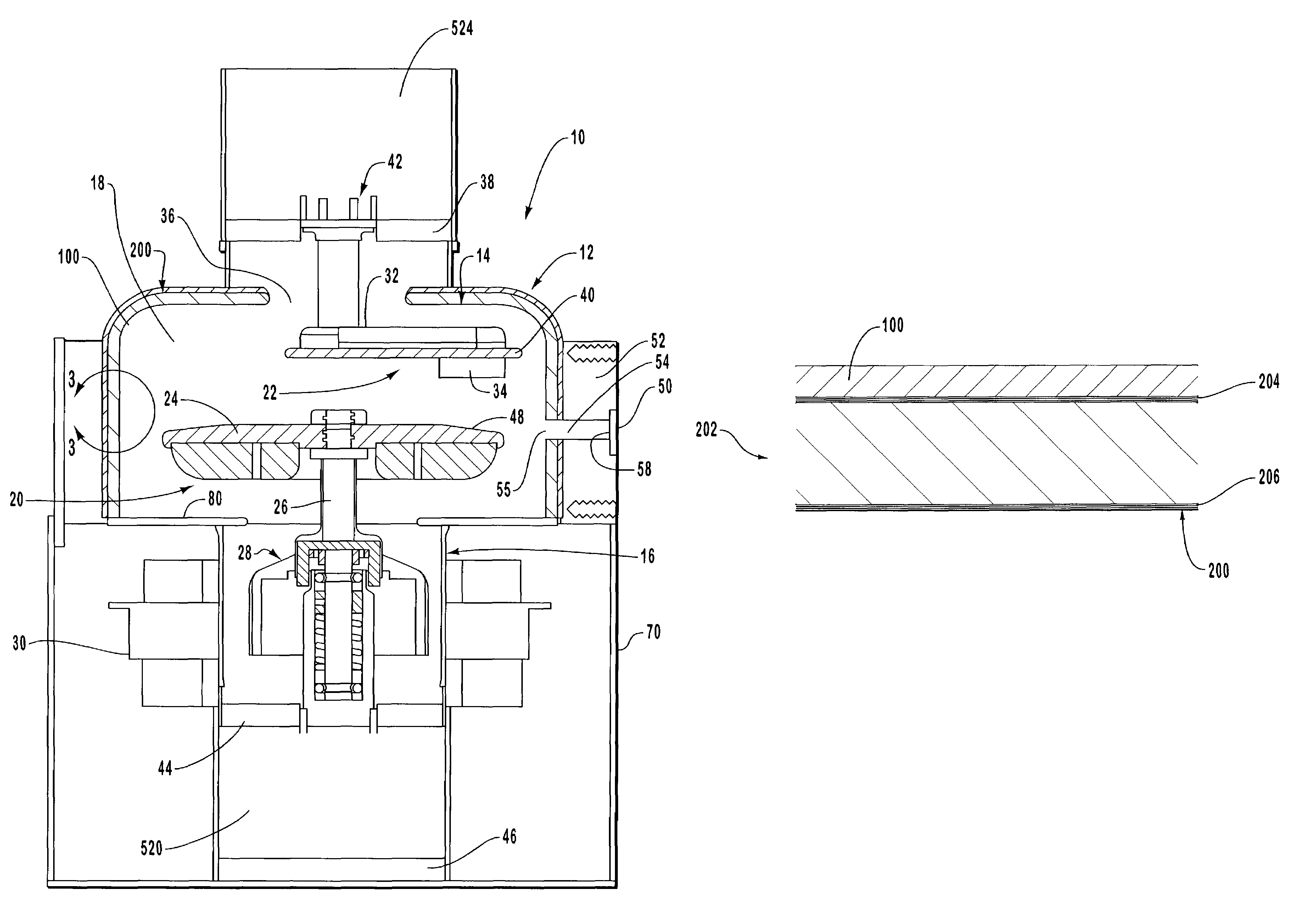
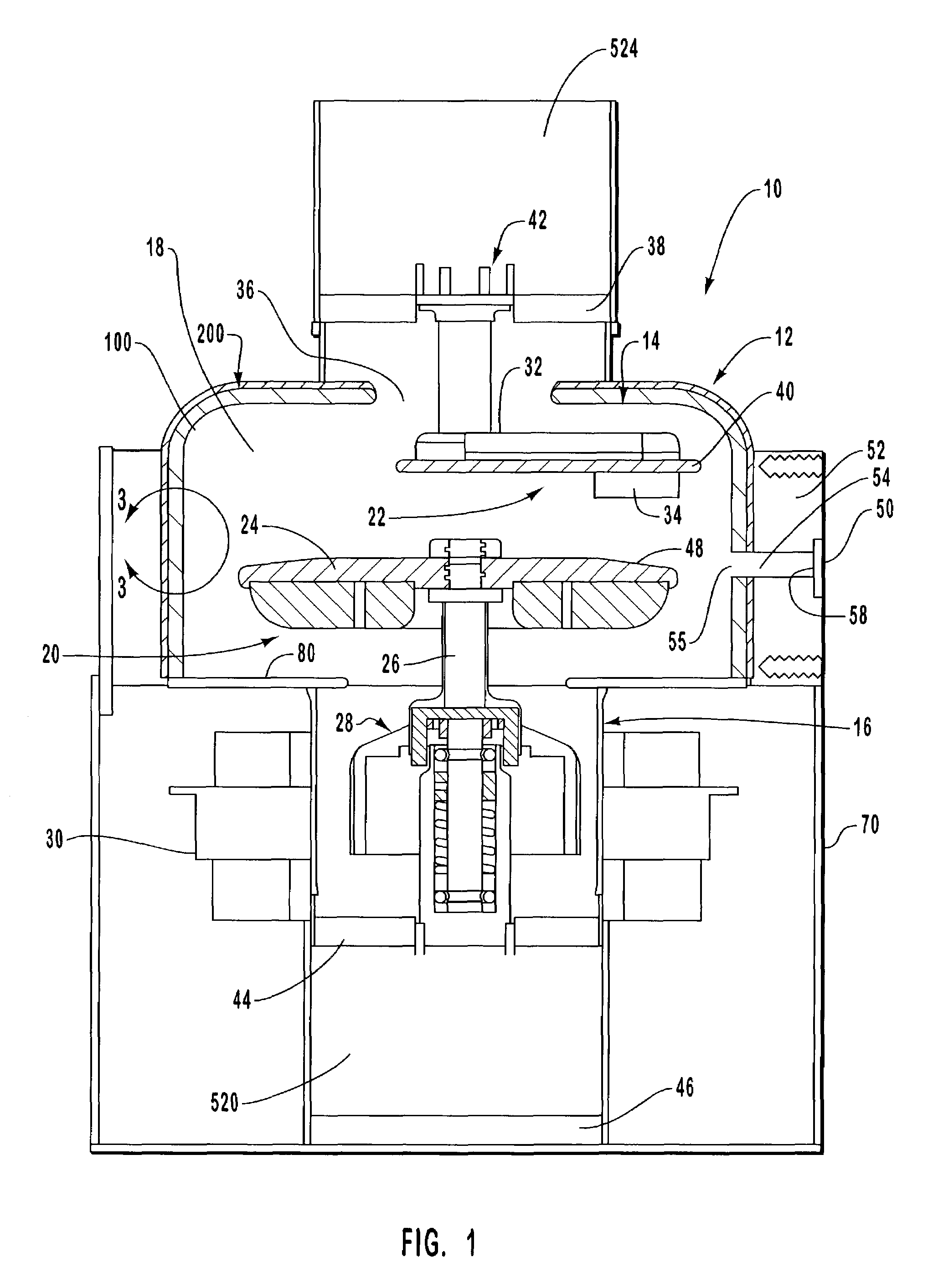
[0041]Reference will now be made to the drawings, wherein exemplary embodiments of the present invention are illustrated. Reference is first made to FIG. 1, which illustrates a cross-sectional view of an example x-ray tube assembly, designated generally at 10, which is constructed with a single housing assembly, designated generally at 12. In the presently preferred embodiment, the housing 12 is formed as a substantially integral housing with a first envelope portion 14 and a second envelope portion 16 joined so as to define an evacuated enclosure 18. Disposed within the vacuum enclosure 18 are the various x-ray tube components, including the rotating anode assembly, designated generally at 20, and the cathode assembly, designated generally at 22. The rotating anode assembly 20 includes an anode target 24 which is connected via a shaft 26 to a rotor assembly 28 for rotation. A stator 30 is disposed outside the integral housing 12 so that it is proximate to the rotor assembly 28, for...


PUM

PropertyMeasurementUnit
voltageaaaaaaaaaa
voltageaaaaaaaaaa
thicknessaaaaaaaaaa

Abstract

The present invention is directed to an air-cooled radiographic apparatus, and its method of manufacture, that utilizes a single integral housing for providing an evacuated envelope for an anode and cathode assembly. The integral housing is preferably formed from a substrate material that has a radiation shielding layer comprising a powder metal that is deposited with a plasma spray process. The powder metal includes, for example, tungsten and iron, so that the radiation shield layer provides sufficient radiation blocking and heat transfer characteristics such that an additional external housing is not required. In one alternative embodiment, the integral housing is composed of a solidified, integrated mixture of metallic powders that function together as both the integral housing wall and the radiation shielding. In another alternative embodiment, chromium is intermixed into the mixture of metallic powders to form a thermally emissive surface upon firing the housing in a wet hydrogen environment.

Description

RELATED APPLICATION INFORMATION[0001]This application is a continuation-in-part of United States patent application entitled “X-ray Tube and Method of Manufacture,” filed on Oct. 23, 2000, and having U.S. Ser. No. 09 / 694,568, now U.S. Pat. No. 6,749,337 which is a continuation-in-part of United States patent application entitled “X-ray Tube and Method of Manufacture,” filed on Jan. 26, 2000 and having U.S. Ser. No. 09 / 491,416 now U.S. Pat. No. 6,619,842. These applications are incorporated herein in their entirety.BACKGROUND OF THE INVENTION[0002]1. The Field of the Invention[0003]The present invention relates to x-ray generating devices and their method of manufacture. More particularly, the present invention relates to an x-ray tube having an evacuated housing assembly that provides enhanced thermal stability and improved x-ray shielding characteristics. The invention also relates to methods of manufacturing the improved housing assembly.[0004]2. The Prior State of the Art[0005]X-...

Claims


Application Information

Patent Timeline
Patent Type & Authority Patents(United States)
IPC IPC(8): H01J35/18
CPCH05G1/025H05G1/04
Inventor MILLER, ROBERT S.SALMON, DEBORAH L.ARTIG, CHRISTOPHER F.
Owner VAREX IMAGING CORP
Why Eureka
Try Eureka