
Light emitting stacked structure and display device having the same

a technology of light emitting diodes and stacked structures, applied in semiconductor devices, semiconductor/solid-state device details, instruments, etc., can solve the problems of increasing manufacturing complexity, large number of micro leds, and difficulty in handling light emitting diodes of small size, so as to increase the light emitting area of each subpixel without increasing the pixel area

Active Publication Date: 2019-06-20
SEOUL VIOSYS CO LTD
View PDF0 Cites 23 Cited by
  • Summary
  • Abstract
  • Description
  • Claims
  • Application Information

AI Technical Summary

Benefits of technology

The invention provides light emitting diodes and displays that have improved color purity and reproduction. This has a simple structure that can improve connectivity between elements and reduce manufacturing complexities.

Problems solved by technology

In addition, a display device using LEDs may be generally manufactured by forming individually grown red, green, and blue LED structures on a final substrate, which may increase manufacturing complexity.
Therefore, a large number of micro LEDs are required to be disposed on one substrate.
However, the micro LED has a very small size having a surface area of 10,000 square μm or less, and thus, there are various problems due to this small size.
Particularly, it is difficult to handle a light emitting diode having a small size, and it is not easy to mount the light emitting diode on a display panel, especially over hundreds of thousands or millions, and to replace a defective LED of mounted micro LEDs with a good LED.
Therefore, in order to arrange the subpixels within a limited area, it is required to reduce the area of each subpixel, thereby causing deterioration in brightness through reduction in luminous area.

Method used


Image

  • Light emitting stacked structure and display device having the same
  • Light emitting stacked structure and display device having the same
  • Light emitting stacked structure and display device having the same

Examples


Embodiment Construction

[0131]In the following description, for the purposes of explanation, numerous specific details are set forth in order to provide a thorough understanding of various exemplary embodiments or implementations of the invention. As used herein “embodiments” and “implementations” are interchangeable words that are non-limiting examples of devices or methods employing one or more of the inventive concepts disclosed herein. It is apparent, however, that various exemplary embodiments may be practiced without these specific details or with one or more equivalent arrangements. In other instances, well-known structures and devices are shown in block diagram form in order to avoid unnecessarily obscuring various exemplary embodiments. Further, various exemplary embodiments may be different, but do not have to be exclusive. For example, specific shapes, configurations, and characteristics of an exemplary embodiment may be used or implemented in another exemplary embodiment without departing from ...


PUM


Abstract

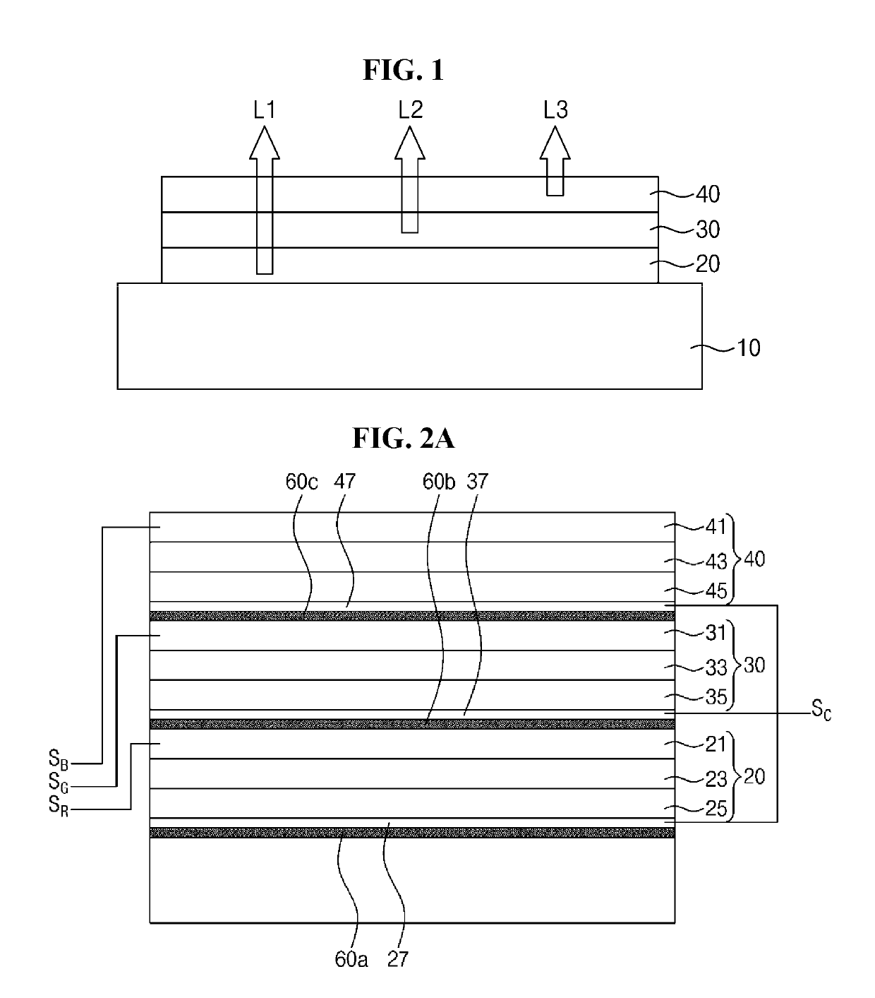
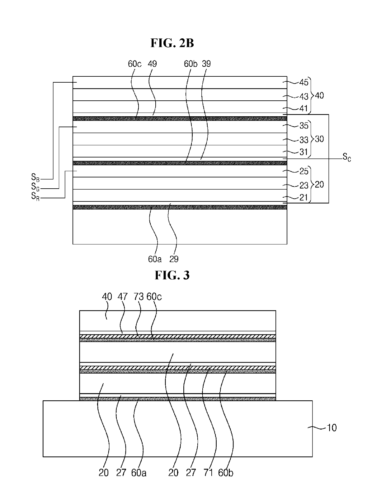
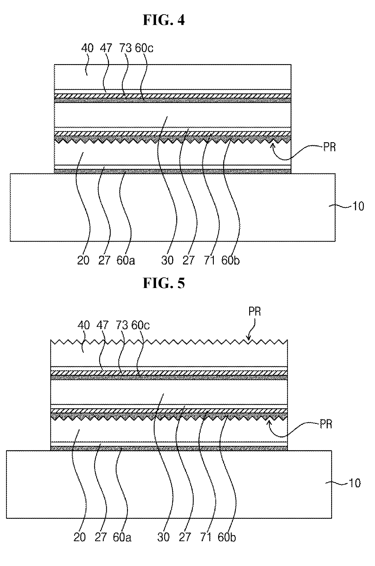
A light emitting stacked structure including a plurality of epitaxial sub-units disposed one over another, each epitaxial sub-unit configured to emit colored light having different wavelength band from each other, and a common electrode disposed between and connected to adjacent epitaxial sub-units, in which light emitting regions of the epitaxial sub-units overlap each other.

Description

CROSS-REFERENCE TO RELATED APPLICATIONS[0001]This application claims priority from and claims the benefit of U.S. Provisional Application No. 62 / 598,863, filed on Dec. 14, 2017, U.S. Provisional Application No. 62 / 598,823, filed on Dec. 14, 2017, and U.S. Provisional Application No. 62 / 617,038, filed on Jan. 12, 2018, each of which is hereby incorporated by reference for all purposes as if fully set forth herein.BACKGROUNDField[0002]Exemplary embodiments of the invention relate generally to a light emitting stacked structure and a display device including the same and, more specifically, to a micro light emitting device having a stacked structure and a display apparatus having the same.Discussion of the Background[0003]A light emitting diode has been widely used as an inorganic light source in various fields such as a display apparatus, an automobile lamp, and general lighting. With advantages of long lifespan, low power consumption, and high response speed, the light emitting diode...

Claims


Application Information

Patent Timeline
IPC IPC(8): H01L27/15H01L33/62H01L33/40H01L33/24H01L25/075G09G3/32G09G3/20
CPCH01L27/153H01L33/62H01L33/405H01L33/24H01L25/0753G09G3/32G09G3/2003G09G2310/08G09G2300/0426H01L33/08H01L33/58H01L27/156H01L33/60H01L23/5286G09G3/3225G09G2300/023H01L25/0756H01L25/075H01L33/38H01L33/504H01L21/02293H01L33/36H01L33/0008H01L27/1214
Inventor CHAE, JONG HYEONJANG, SEONG GYULEE, HO JOON
Owner SEOUL VIOSYS CO LTD
Learn More