Thrust reverser assembly and method of operation

a thrust reverser and assembly technology, applied in the field of high-bypass gas turbine engines, can solve the problems of engine noise attenuation, engine performance reduction, engine damage and wear, etc., to reduce aerodynamic and/or acoustic efficiency, reduce damage/wear, and reduce aerodynamic drag

Active Publication Date: 2013-10-31
MRA SYST LLC
View PDF3 Cites 25 Cited by
  • Summary
  • Abstract
  • Description
  • Claims
  • Application Information

AI Technical Summary

Benefits of technology

[0009]A technical effect of the invention is that blocker doors of the thrust reverser assembly can be completely stowed within the nacelle of the engine, such that the blocker doors are concealed by the fan duct flow surface defined by the translating cowl. As a result, the blocker doors are only exposed during use of the thrust reverser system and therefore have reduced exposure to damage / wear inducing conditions. The invention is also capable of significantly reducing aerodynamic drag and other flow perturbations that would be otherwise attributed to the blocker doors and their associated link arms, which reduce aerodynamic and / or acoustic efficiency. Notably, concealment of the blocker doors in this manner also facilitates the ability to acoustically treat essentially all of the flow surfaces that define the fan duct outer flow path in the critical area immediately aft of the engine fan. The thrust reverser assembly achieves these results while also being capable of having reduced design complexity, manufacturing complexity, cost, and weight associated with the assembly and its components, including the blocker doors, translating cowl, and fixed structure of the nacelle.
[0010]Other aspects and advantages of this invention will be better appreciated from the following detailed description.

Problems solved by technology

A drawback of this type of conventional construction is that the blocker doors 34C define portions of the fan duct outer flow surfaces, and surface interruptions (gaps and steps) and duct leakage resulting from the doors 34C can increase aerodynamic drag and reduce aerodynamic performance.
In addition, the blocker doors 34C incorporate only limited areas of acoustic treatment as well as create discontinuities in the translating cowl acoustic treatment, and are exposed to damage and wear-inducing conditions during normal engine operation.
These aspects of conventional thrust reversers can significantly reduce engine performance, engine noise attenuation, specific fuel consumption, and operational reliability.

Method used


Image

  • Thrust reverser assembly and method of operation
  • Thrust reverser assembly and method of operation
  • Thrust reverser assembly and method of operation

Examples


Embodiment Construction

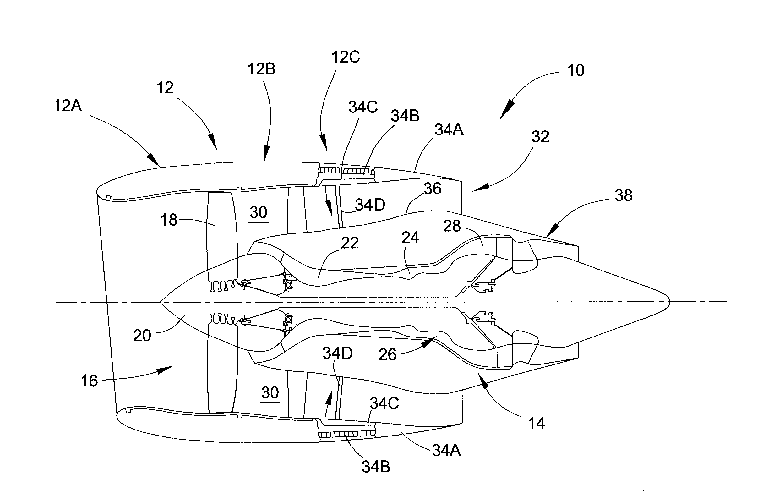
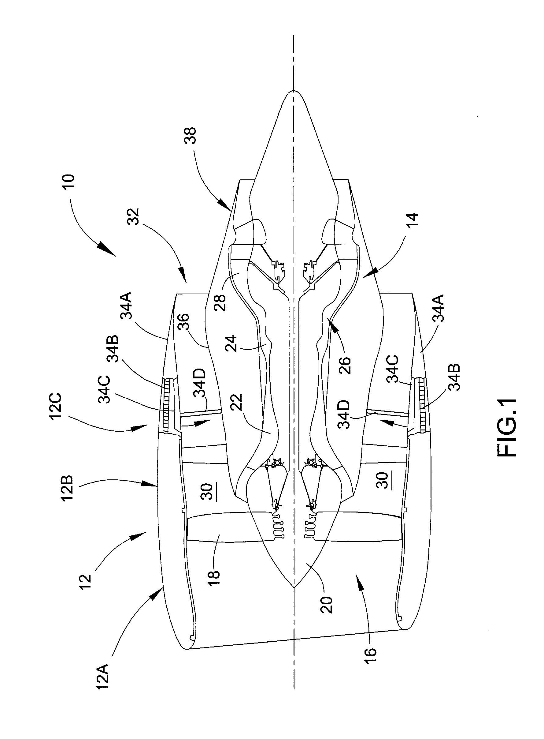
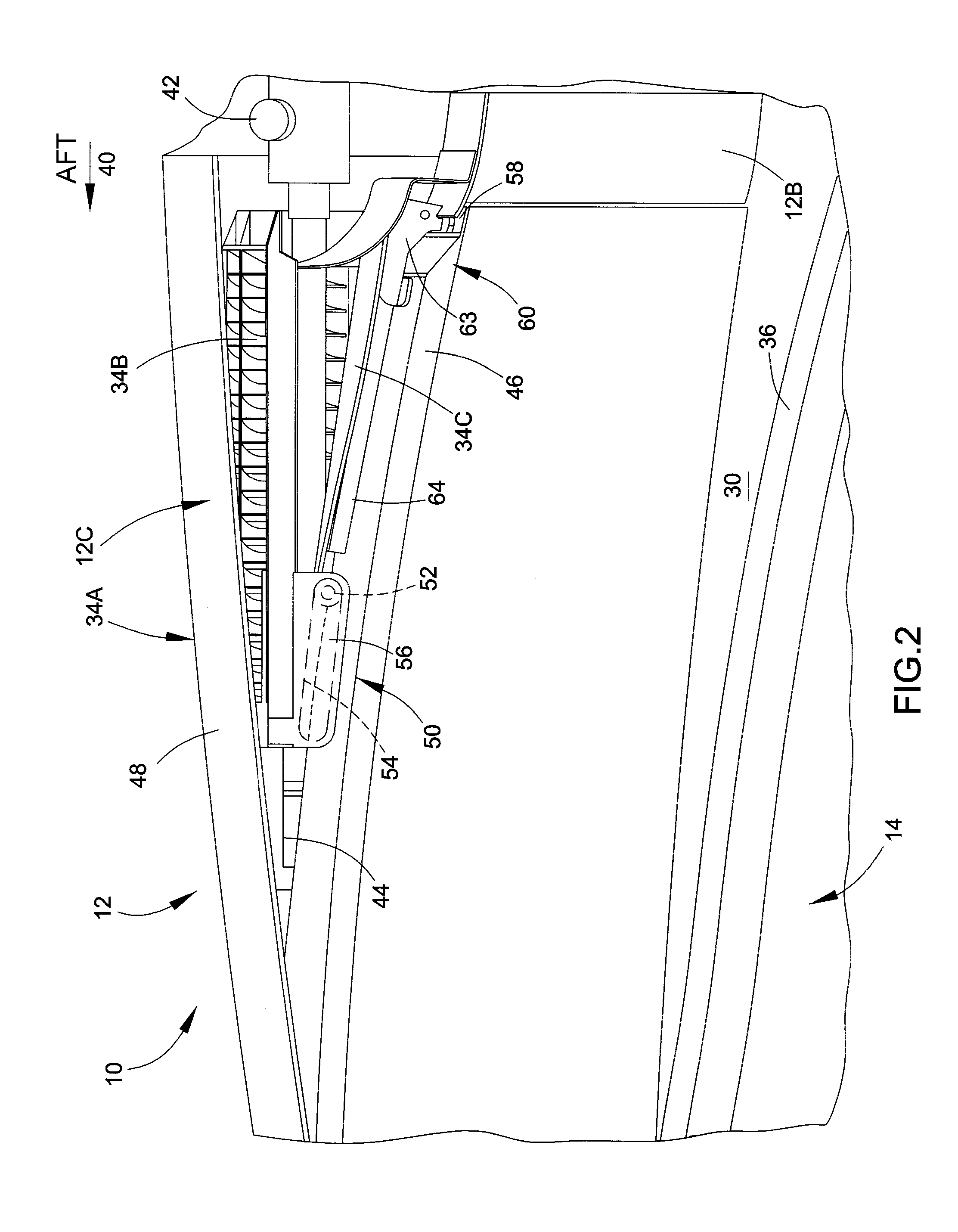
[0014]FIGS. 2 through 5 represent views of a region of a gas turbine engine containing a thrust reverser assembly. The thrust reverser assembly represented in FIGS. 2 through 5 can be installed in a high-bypass gas turbofan engine of the type represented in FIG. 1 and therefore, as a matter of convenience, the same numbers used in FIG. 1 to identify the engine 10 and its components will be used in FIGS. 2 through 5 to identify the same or functionally equivalent components. As such, it should be understood that FIGS. 2 through 5 depict a thrust reverser assembly 12C located within the nacelle 12 of the engine 10 and aft of the fan cowl 12B. It should be further understood that a core cowl 36 defines the radially inward boundary of a bypass duct 30, the nacelle 12 defines the radially outward boundary of the bypass duct 30, and bypassed air of the engine 10 passes through the bypass duct 30 and exits through a fan exit nozzle 32 (not shown in FIGS. 2 through 5). Other structural and ...


PUM


Abstract

A thrust reverser assembly and operation suitable for high-bypass turbofan engines. The thrust reverser assembly includes a translating cowl mounted to a nacelle of an engine and adapted to translate in an aft direction of the engine. The translating cowl has a radially inner wall that defines a radially outer flow surface of a bypass duct of the engine. The thrust reverser assembly includes blocker doors axially guided adjacent first ends thereof by a fixed structure and pivotally and slidably connected along lengths thereof to the inner wall of the translating cowl so that translation of the translating cowl in the aft direction causes each blocker door to move from a stowed position to a deployed position as a result of the blocker door sliding at its first end relative to the fixed structure and sliding along its length relative to the inner wall of the translating cowl.

Description

BACKGROUND OF THE INVENTION[0001]The present invention relates to high-bypass gas turbine engines, and more particularly to thrust reversers utilized in high-bypass turbofan engines to provide thrust reversal by diverting air from a fan bypass duct.[0002]FIG. 1 schematically represents a high-bypass turbofan engine 10 of a type known in the art. The engine 10 is schematically represented as including a nacelle 12 and a core engine (module) 14. A fan assembly 16 located in front of the core engine 14 includes a spinner nose 20 projecting forwardly from an array of fan blades 18. The core engine 14 is schematically represented as including a high-pressure compressor 22, a combustor 24, a high-pressure turbine 26 and a low-pressure turbine 28. A large portion of the air that enters the fan assembly 16 is bypassed to the rear of the engine 10 to generate additional engine thrust. The bypassed air passes through an annular-shaped bypass duct 30 between the nacelle 12 and an inner core co...

Claims


Application Information

Patent Timeline
Patent Type & Authority Applications(United States)
IPC IPC(8): B63H11/10
CPCF02K1/70F02K3/06F05D2260/50F05D2240/91Y02T50/60
Inventor HOWARTH, GRAHAM FRANKHUGHES, BRYAN WAYNE
Owner MRA SYST LLC
Why Eureka
Try Eureka