Cantilevered screw assembly

a technology of cantilever screw and assembly, which is applied in the direction of packaging, etc., can solve the problems of reducing the size of the screw and the amount of material that can be processed, limiting the load-bearing capacity, and affecting the operation of the assembly, so as to reduce the weight of the assembly, reduce the excess material, and reduce manufacturing and assembly costs

Active Publication Date: 2017-11-21
KOMAR IND LLC
View PDF75 Cites 1 Cited by
  • Summary
  • Abstract
  • Description
  • Claims
  • Application Information

AI Technical Summary

Benefits of technology

[0004]Needs also exist to reduce the weight and manufacturing complexity of cantilevered screw assemblies. Some known cantilevered screw assemblies simply increase the girth of a load-bearing wall or include a series of bracing members in an attempt to increase the assemblies' load-bearing capacity. The assemblies of some known cantilevered screw assemblies also require many separate parts to be welded or otherwise assembled together to create the cantilevered screw assembly. This requires additional design and manufacturing complexity, including time, material, equipment, and labor resources to manufacture the assembly. Further, the additional fasteners, weld material, and other assembly devices add more weight to the assembly.
[0006]More specifically, in an exemplary embodiment, the cantilevered screw assembly includes a wall and at least a portion of a bearing housing that are formed as a one-piece unit. For example, the wall may be cast with at least a portion of the bearing housing in an exemplary embodiment. In one example, the bearing housing may comprise a body, a flared edge, a plurality of flanges, and / or a number of receptacles that are formed of a one-piece unit (e.g. a single casting) with the support wall, thereby eliminating the need to manufacture and assemble these parts separately. In an exemplary embodiment, the single casting may reduce manufacturing and assembly costs when compared to assemblies requiring that these parts be manufactured separately and assembled. This may additionally reduce excess material such as weld material, fasteners, other assembly devices, or other excess material otherwise required to manufacture the assembly, which may reduce the weight of the assembly. Further, this may eliminate or lessen the need for increased girth of the walls or additional bracing members. This may also allow for increased strength and rigidity of a comparable or lesser weight assembly.
[0007]Examples of the improved support wall assembly may allow for a larger screw without compromising stability or the integrity of the load-bearing wall. Also, exemplary embodiments may enable more material to be processed by the cantilevered screw assembly with greater power and torque. Exemplary embodiments may further allow for reduced construction costs and assembly size when compared to assemblies requiring additional walls or other large assemblies for cantilevering the screw assembly.

Problems solved by technology

The screws of some known cantilevered screw assemblies have a tendency to shift in position or wobble during operation.
The anchoring of known cantilevered screw assemblies may also limit load-bearing capacity.
The load-bearing wall may limit the size of the screw and the amount of material that can be processed.
If the size of the screw is excessive, it may compromise the load-bearing wall.
For example, it may lead to oil canning of the load-bearing wall.
Oil canning may affect the operation of the screw as aforementioned, and it may eventually render the system inoperable.
This requires additional design and manufacturing complexity, including time, material, equipment, and labor resources to manufacture the assembly.
Further, the additional fasteners, weld material, and other assembly devices add more weight to the assembly.

Method used


Image

  • Cantilevered screw assembly
  • Cantilevered screw assembly
  • Cantilevered screw assembly

Examples


Embodiment Construction

)

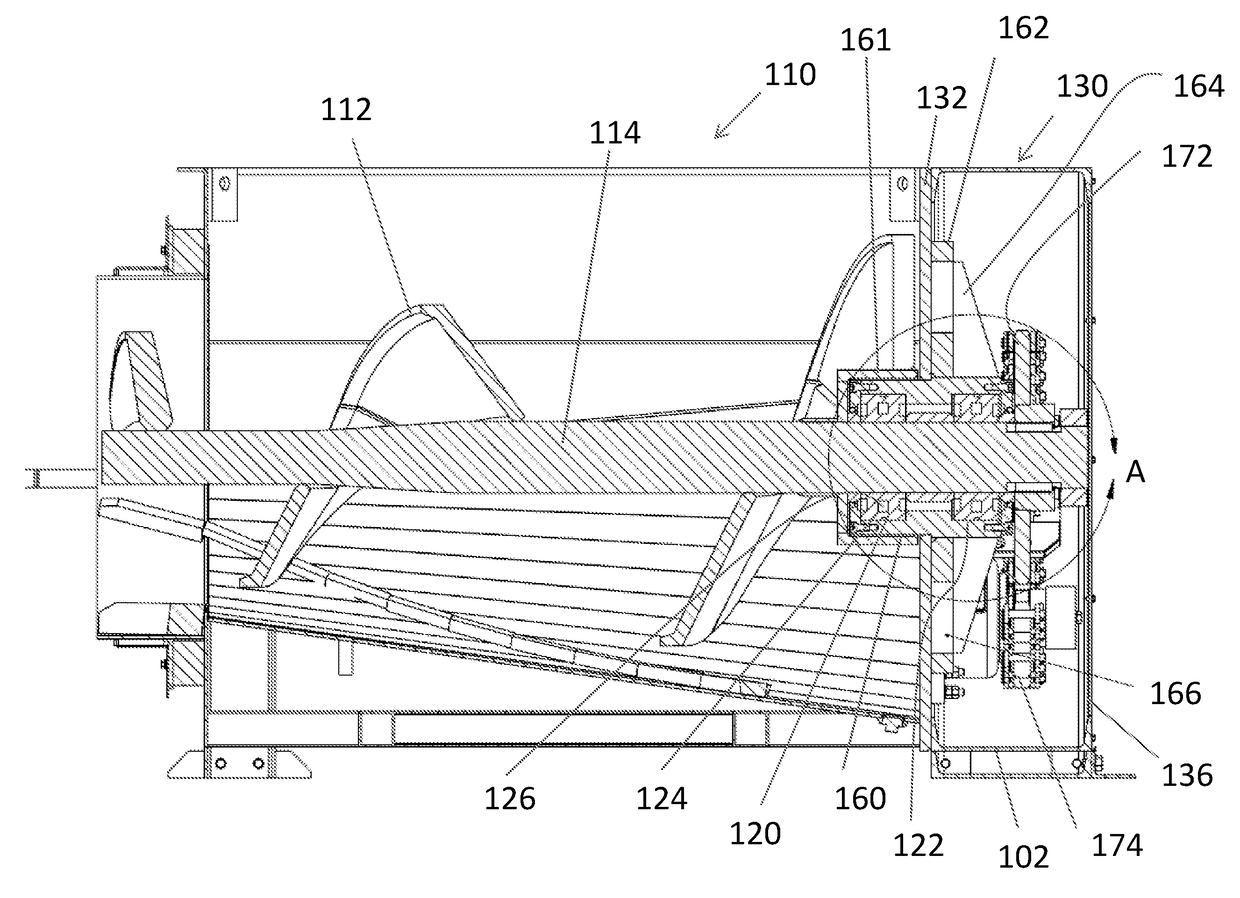
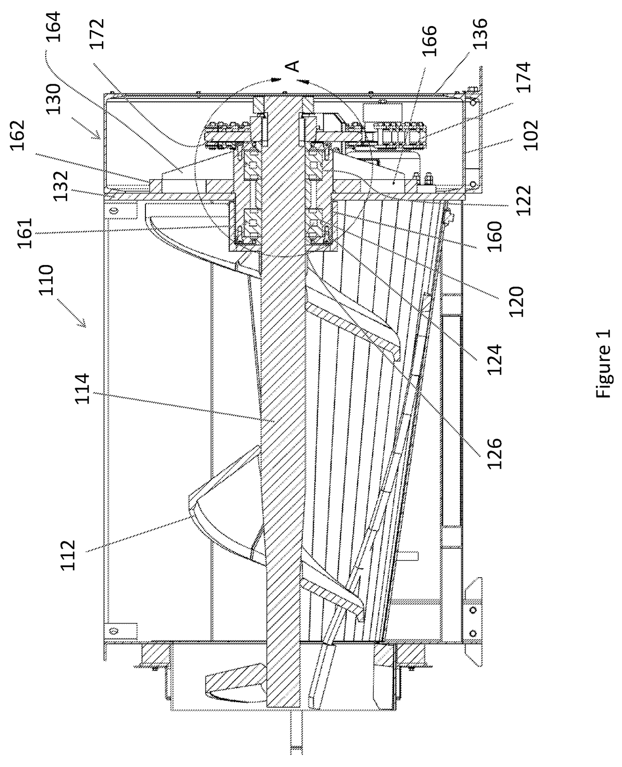
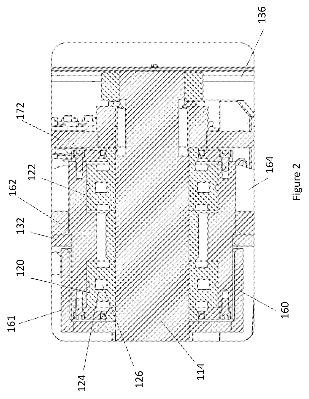
[0017]Exemplary embodiments of the present invention are directed to a cantilevered screw assembly. FIGS. 1-4 show various views of an exemplary embodiment of a cantilevered screw assembly 110 comprising a screw 112, which has a shaft 114. While this embodiment of shaft 114 has a slight taper, other types of cantilevered screw assemblies may also benefit from aspects of the present invention. For instance, some embodiments may not have a shaft with a taper, while other embodiments may have a shaft with a reverse taper. For embodiments that have a shaft with a taper or reverse taper, the degree of the taper or reverse taper may be selected to fit the application of the cantilevered screw assembly.

[0018]In the present exemplary embodiment, screw 112 is cantilevered to a wall of a multiple wall assembly 130. In this exemplary embodiment, the multiple wall assembly 130 is comprised of a first wall 132 to which bearings are mounted and the screw 112 is cantilevered. This exemplary embod...


PUM


Abstract

A cantilevered screw assembly comprising an improved support wall assembly. In an exemplary embodiment, a support wall may be formed of a single casting with at least a portion of a bearing housing.

Description

BACKGROUND AND SUMMARY OF THE INVENTION[0001]Exemplary embodiments of the present invention relate generally to a cantilevered screw assembly. Examples of cantilevered screw assemblies may include, but are not limited to, augers, compactors, crushers, shredders, feeders, material handlers, bale breakers, briquetters, and autoclave sterilizers. Other applications of cantilevered screw assemblies are also possible.[0002]There is a need to improve known cantilevered screw assemblies. Large scale cantilevered screw assemblies are in particular need of improvement due to the dynamics of such systems. Nevertheless, small scale cantilevered screw assemblies may have a similar need for improvement.[0003]For example, needs exist to improve the stability, size, and load-bearing capacity of cantilevered screw assemblies. The screws of some known cantilevered screw assemblies have a tendency to shift in position or wobble during operation. The anchoring of known cantilevered screw assemblies ma...

Claims


Application Information

Patent Timeline
Patent Type & Authority Patents(United States)
IPC IPC(8): B65G33/32
CPCB65G33/32
Inventor KOENIG, MARK E.KOENIG, LARRY E.
Owner KOMAR IND LLC
Why Eureka
Try Eureka