
Lightning arrester device for low-voltage network

a low-voltage network and arrester technology, applied in emergency protective arrangements for limiting excess voltage/current, emergency protective arrangements for automatic disconnection, electrical equipment, etc., can solve the problems of high risk, arc struck in spark gaps will damage the latter, and the latter will no longer be able to fulfill its protective role, etc., to achieve enhanced surge rating

Inactive Publication Date: 2005-08-16
CITEL
View PDF7 Cites 16 Cited by
  • Summary
  • Abstract
  • Description
  • Claims
  • Application Information

AI Technical Summary

Benefits of technology

[0019]Although, in principle, the solution afforded by this disclosure does not make it possible to increase the intrinsic value of the maximum discharge current permitted for the lightning arrester device, the experiments performed by the applicant with diverse designs of spark gaps have shown that the invention nevertheless makes it possible to improve the surge current rating of the lightning arrester device.
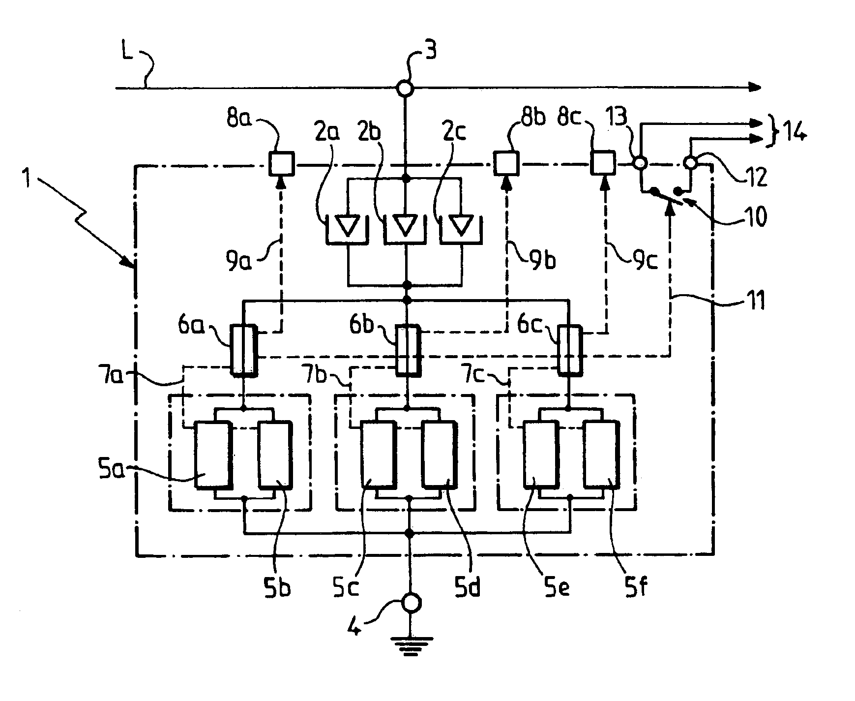
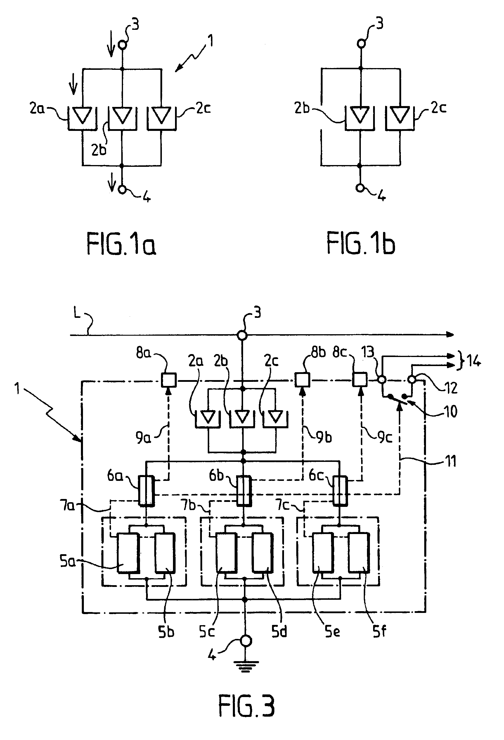
[0023]As an additional explanation of the phenomenon, it may be imagined that the electric arc engendered in the spark gap which tripped first creates an intense magnetic field and / or an intense spark which encourages the creation of a plasma in the adjacent spark gap(s) and, thereby, encourages their tripping. In this case, the current surge wave created by the transient overvoltage can flow through the two or three tripped spark gaps. This has the effect of dividing the intensity of the current crossing each of the tripped spark gaps by two or three and, thereby, of improving the surge current rating of the lightning arrester device.

Problems solved by technology

On the other hand, if the current surge wave exhibits characteristics above the surge current rating of the spark gap activated, there is a high risk that the electric arc struck in the spark gap will damage the latter.
For example, it will go from 300 volts to 700 volts or more, so that, if a transient overvoltage whose amplitude is below the new trip voltage of the spark gap then occurs, the latter will no longer be able to fulfill its role as a protective element.
The electric arc may even damage the spark gap to such a point that it is subsequently totally incapable of tripping in the event of an overvoltage (non-tripping state).
Transient overvoltages are a phenomena which most often occur in a manner which is completely unpredictable in time, and whose intensity cannot be predicted either.
Such gas-type spark gaps exist on the market.
They nevertheless have the drawback of being much bulkier and much more expensive than gas-type spark gaps having a smaller surge current rating, such as those cited earlier by way of example.

Method used


Image

  • Lightning arrester device for low-voltage network
  • Lightning arrester device for low-voltage network
  • Lightning arrester device for low-voltage network

Examples


Embodiment Construction

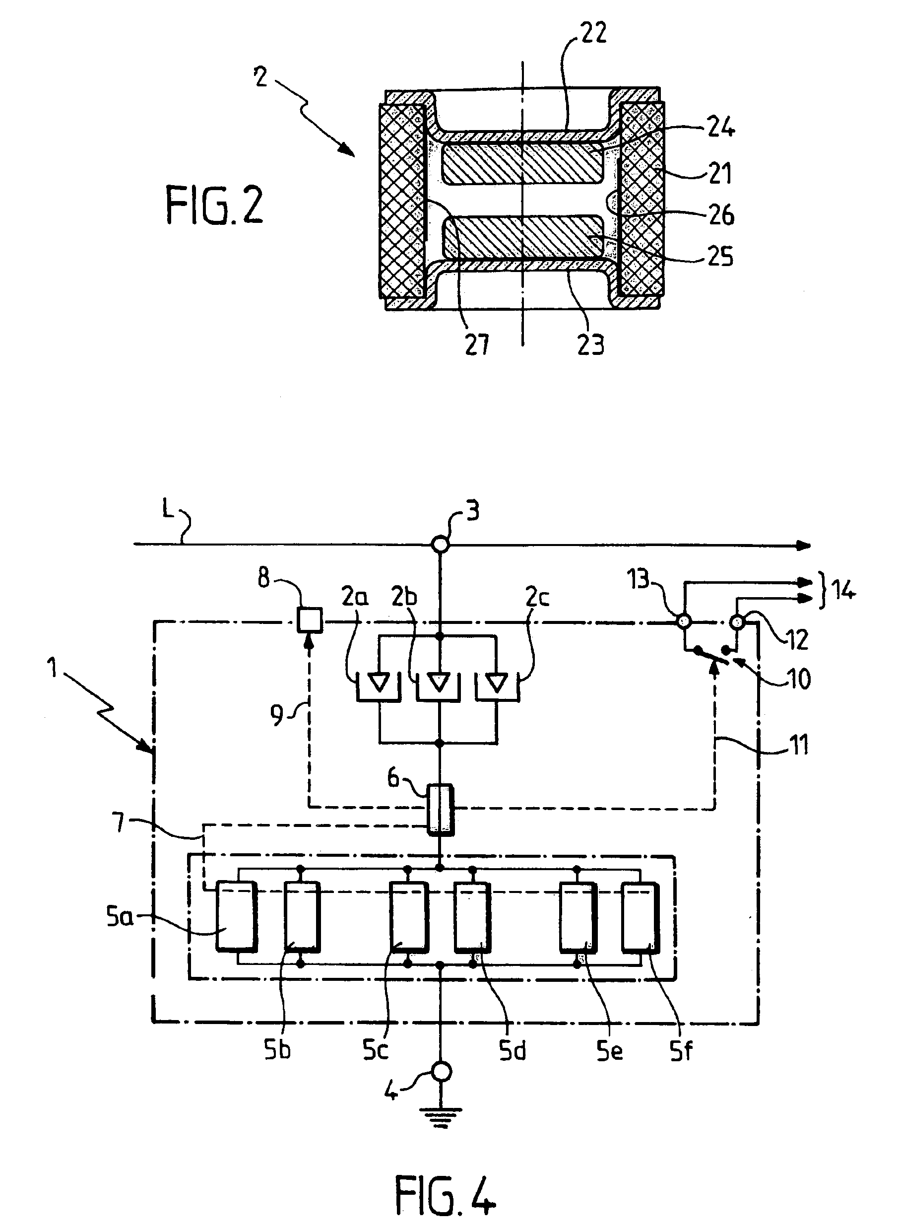
[0035]Turning to FIG. 1a, lightning arrester device 1 according to an embodiment of the invention includes several gas-type spark gaps, for example three spark gaps 2a, 2b and 2c, connected in parallel between two wiring terminals 3 and 4. Terminal 3 is intended to be wired to a line (phase or neutral) of an electrical circuit to be protected, while terminal 4 is intended to be wired to earth, preferably by way of current-limiter elements, as will be described later with reference to FIG. 3.

[0036]Each of the three spark gaps 2a, 2b and 2c can have a structure similar to that of the spark gap 2 represented in FIG. 2. The spark gap 2 includes a small ceramic tube 21, which has, for example, an outside diameter of 8 mm and a length of around 6 mm, and which is filled with a rare gas. The ends of the tube 21 are hermetically sealed by conducting metal dishes 22 and 23 which serve as contact terminals or connection terminals when the spark gap is in service. The ends of the tube 21 are m...


PUM


Abstract

A lightning arrester device for protecting an electrical circuit connected to a low-voltage network against transient overvoltages includes a plurality of gas-type spark gaps each connected directly in parallel with each other across two common nodes. Each of the plurality of gas-type spark gaps individually has a surge current rating below a desired surge current rating of the device.

Description

CROSS-REFERENCE TO RELATED APPLICATIONS[0001]This application is a continuation-in-part (CIP) application of application Ser. No. 09 / 715,183, filed on Nov. 20, 2000 now abandoned by Christian Macanda, entitled “Lightning Arrestor Device for Low-Voltage Network”, the entire contents of which are incorporated herein by reference, and for which benefit is claimed under 35 U.S.C. §120, and for which priority is claimed under 35 U.S.C. §119 to French patent application 99-14556, filed Nov. 19, 1999.BACKGROUND OF THE INVENTION[0002]This disclosure relates to a lightning arrester device for protecting an electrical circuit connected to a low-voltage network against transient overvoltages, of the type comprising at least one protective element consisting of a gas-type spark gap.[0003]Gas-type spark gaps are elements which normally have a very high insulation resistance, which it is possible to regard as being almost infinite, and which trip abruptly and become conducting with a very low res...

Claims


Application Information

Patent Timeline
Patent Type & Authority Patents(United States)
IPC IPC(8): H01T4/12H02H9/06H01T4/00H02H3/05
CPCH01T4/12H02H9/06H02H3/05
Inventor MACANDA, CHRISTIAN
Owner CITEL
Learn More