Clamp for weapon mount

a weapon mount and clamping technology, applied in the field of weapons mounts, can solve the problems of user eye position, lack of quick attachment/release mechanism, and inability to mount the an/pvs-14 properly

Inactive Publication Date: 2005-08-23
ITT MFG ENTERPRISES LLC
View PDF18 Cites 101 Cited by
  • Summary
  • Abstract
  • Description
  • Claims
  • Application Information

AI Technical Summary

Benefits of technology

[0013]The structure described above may be used to position the night vision device above the BUIS, providing clearance for the BUIS restrictive space envelope, and enabling the correct fore / aft positioning of the night vision device on the weapon receiver rail for optimal shooting location and eye relief distance.
[0014]In accordance with a second aspect of the invention, a self-adjusting cam is provided to allow for quick mounting / removal of the weapon mount to the weapon.

Problems solved by technology

The prior art weapon mounts do not allow for proper mounting of the AN / PVS-14 when used in conjunction with the Back-up Iron Sight (BUIS).
However, if the night vision device is physically in front of the BUIS, the sight is too far forward and the user is unable to position his eye at the desired eye relief distance of the sight while maintaining his natural shooting position.
(a) They do not vertically align the AN / PVS-14's optical axis with the M68 Close Combat Optic;
(b) They do not possess a quick attachment / release mechanism that will accommodate maximum to minimum dimension Picatinny Rails (the nickname for the standard M16 / M4 receiver rail).
(c) They employ either complicated ratcheting mechanisms or a non-compensating cam for rail variation to attach the night vision device to the weapon's receiver rail;
(d) They utilize a thumbscrew attachment for securing the weapon mount to the night vision device which is either of a multi-piece design assembled with screw fasteners, or does not have a permanent retention to the mount.
(e) They do not allow the combined mounting of the AN / PVS-14 with a 3× Magnifier Lens, M68 Close Combat Optic and BUIS on a single M16 / M4 receiver rail; and
(f) They will not fit on a standard Weaver Rail in addition to the Picatinny Rail because they employ a #10 rail bolt or rectangular-slot locating bar of similar size as the rail / slot interface.

Method used


Image

  • Clamp for weapon mount
  • Clamp for weapon mount
  • Clamp for weapon mount

Examples


Embodiment Construction

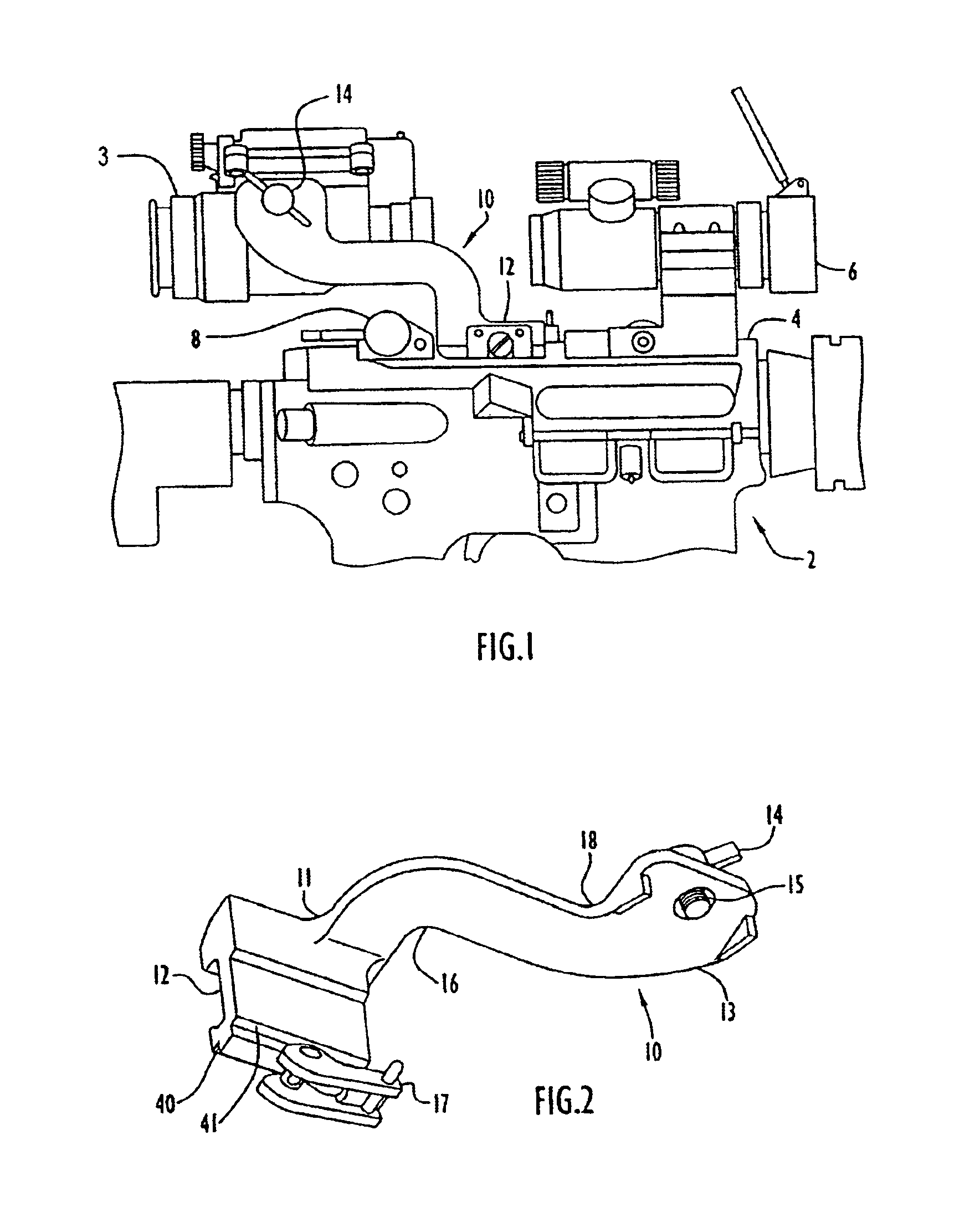
[0027]Referring to FIG. 1, a weapon 2 having a receiver rail 4 is shown. The cross-section of the receiver rail 4 is shown more clearly in FIG. 8. In the preferred embodiment, the receiver rail is the M16 / M4 receiver rail, although the invention may be employed in connection with other receiver rails also.

[0028]A backup iron sight (BUIS) 8 is mounted on the weapon and in fact, the U.S. military desires that the BUIS be constantly mounted on the weapon during daytime and nighttime operations. Since the BUIS Is mounted at the extreme rear of the weapon's receiver rail, the night vision device must be mounted in front of the BUIS on the weapon's receiver rail. However, in this case, without the use of the present invention, the sight is too far forward and the user is unable to position his eye at the desired eye relief distance of the sight and maintain his natural shooting distance.

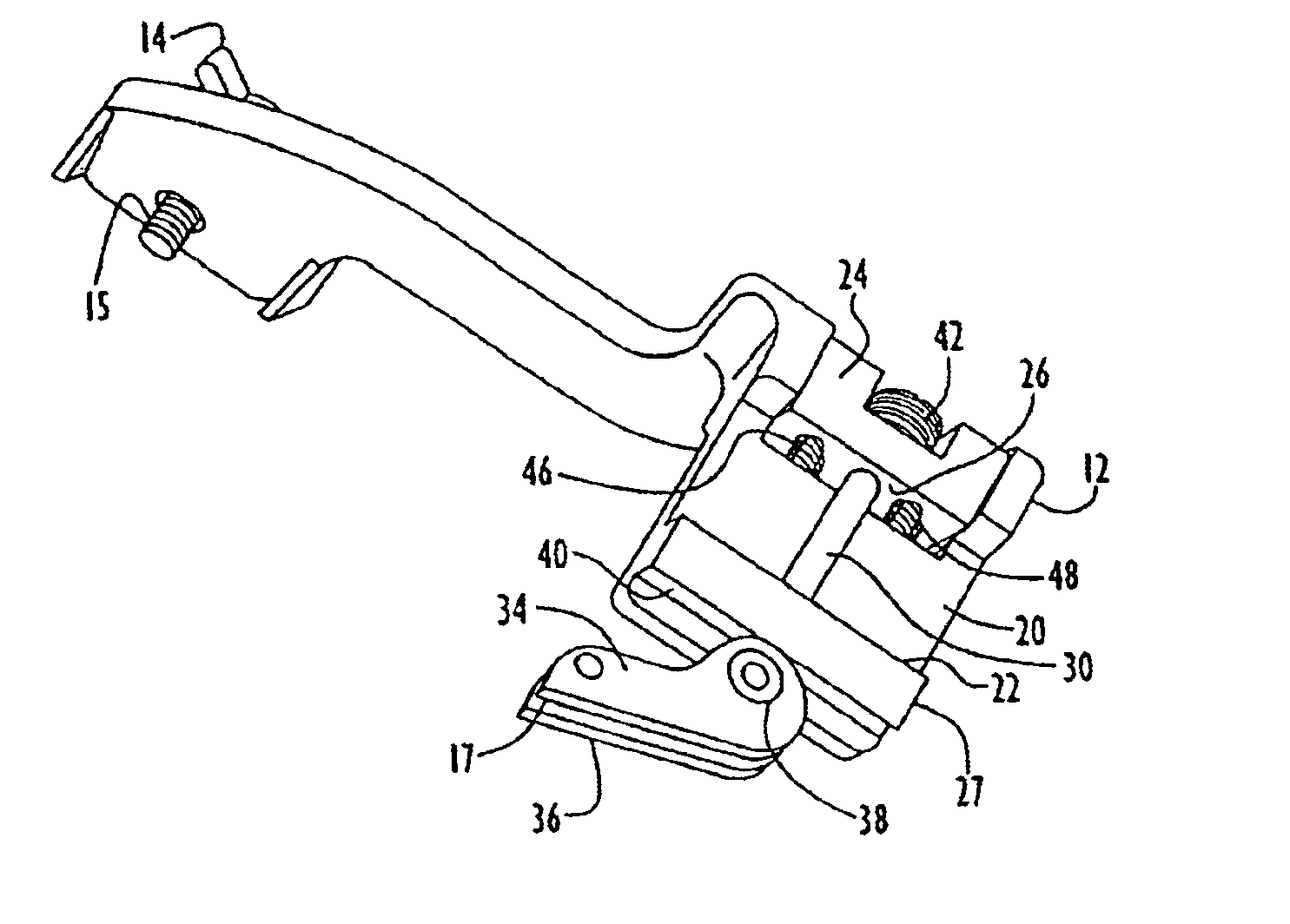
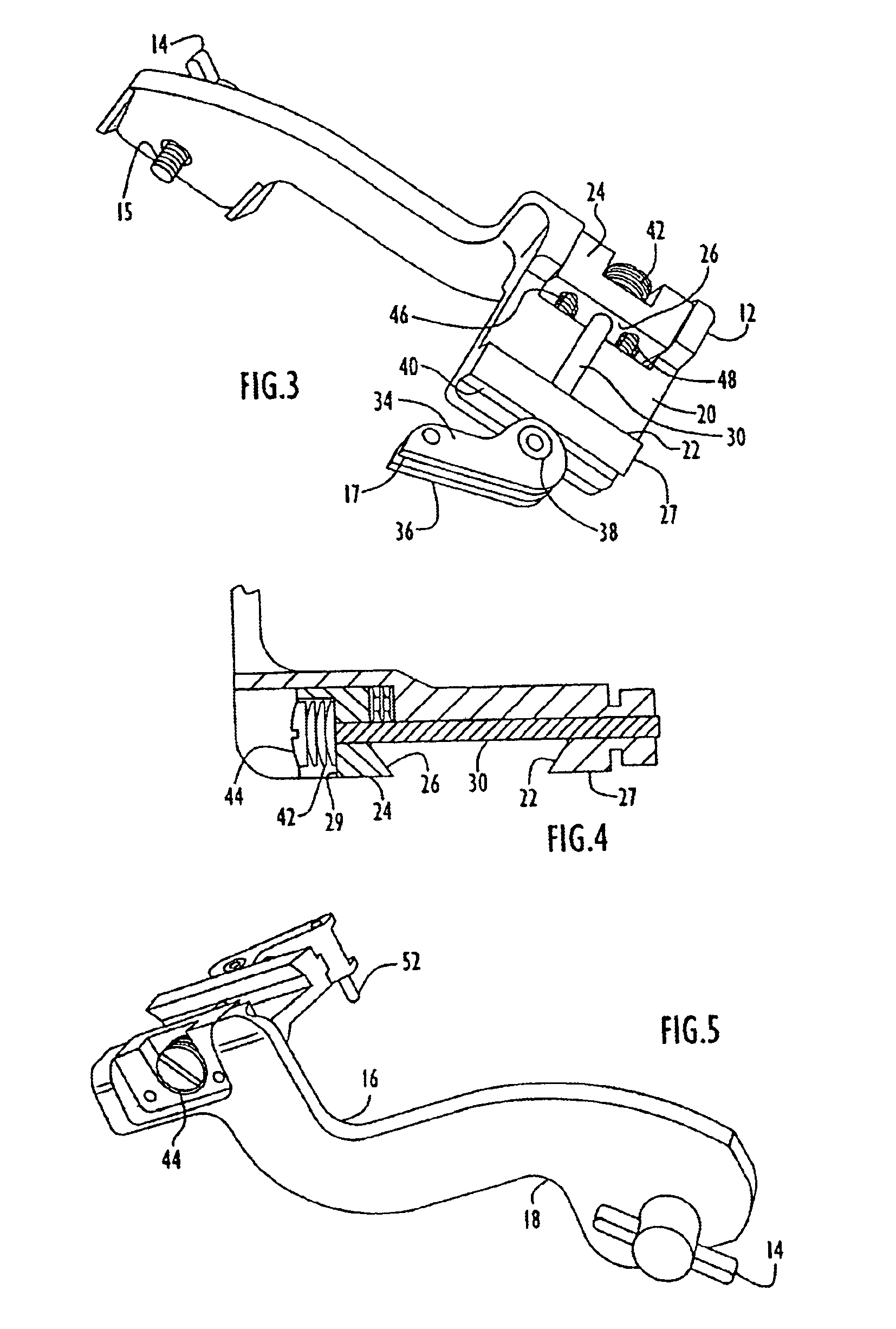
[0029]In accordance with an aspect to the invention, a mounting member 10 is provided, which is arrange...


PUM


Abstract

A weapon mount for mounting a night vision device to the receiver rail of a weapon. A self-device adjusting cam operated connection device is present at one end region of the mount for attaching to the receiver rail, while the night vision device is connected at the other end region of the mount with a knob operated mounting screw. The knob and mounting screw are a one piece design and the mounting screw is captivated by an E-clip. The cam operated connection device may be adjusted to accommodate different size receiver rails by the provision of compressible means, such as Belleville washers.

Description

[0001]The present application is a divisional of U.S. application Ser. No. 09 / 847,293 filed May 3, 2001, now U.S. Pat. No. 6,637,144, which is incorporated herein by reference in its entirety.FIELD OF THE INVENTION[0002]The present invention is directed to a weapon mount for mounting an auxiliary device such as a night vision device to the receiver rail of a weapon, such as a rifle.BACKGROUND OF THE INVENTION[0003]It is known to mount a night vision device on a weapon such as a rifle to enable a soldier to accurately aim the weapon in darkness. Weapon mounts for such purpose include means for fastening the night vision device to the mount, and for fastening the mount to the weapon's receiver rail. It is important for the mounting devices to be easy and quick to operate while providing a secure and robust mechanical attachment. In order for the shooter to maintain his normal shooting position, a suitable weapon mount must also provide proper vertical positioning of the night vision d...

Claims


Application Information

Patent Timeline
Patent Type & Authority Patents(United States)
IPC IPC(8): F41G1/387F41G1/35F41G1/00
CPCF41G1/35F41G11/003
Inventor NELSON, JOHN CARLLESNIOWSKI, STEPHEN
Owner ITT MFG ENTERPRISES LLC
Why Eureka
Try Eureka