Controlled truck cab suspension system

Active Publication Date: 2006-07-18
DELPHI TECH INC +1
View PDF26 Cites 32 Cited by
  • Summary
  • Abstract
  • Description
  • Claims
  • Application Information

AI Technical Summary

Benefits of technology

[0006]The present invention is a controlled suspension system particularly adapted to provide a rear mount for a truck or tractor cab on an associated vehicle frame. The suspension system preferably includes a strut having an air sleeve and adapted to be attached at one end to a truck cab and at an opposite end to an associated truck frame, a height sensor adapted to be attached to the cab and frame for measuring a distance ther

Problems solved by technology

A disadvantage with such prior art systems is that they are overly complex, relatively expensive and occupy

Method used


Image

  • Controlled truck cab suspension system
  • Controlled truck cab suspension system
  • Controlled truck cab suspension system

Examples


Example

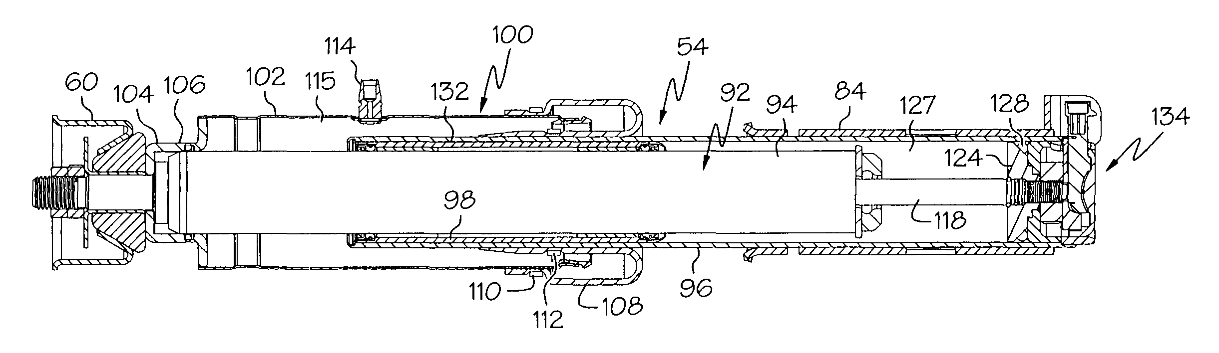
[0025]One embodiment of the present invention, generally designated 50, is shown in FIGS. 4, 5, 6 and 7. Struts 52, 54, preferably McPherson-type struts, are mounted noncompliantly (i.e., rigidly) to the insides of frame rails 18, 20, preferably to flanges 56 (only one of which is shown) attached to the rails. Resilient mounts 58, 60 attach the struts 52, 54 to the rear 24 of the cab 16. The resilient mounts 58, 60 may be of any design that allows for angular compliance (i.e. pivotal movement of the struts 52, 54 relative to the cab 16) while restricting lateral and vertical compliance.

[0026]At least one height sensor 62 is mounted on a transverse member 64 extending between rails 18, 20 and is attached by a link 66 to the cab 16 to measure the height of the cab above the frame rails. The height sensor 62 is of conventional design and alternately may be mounted on the cab 16 and have a link to the member 64.

[0027]A controller 68 of conventional design is connected by electrical cond...


PUM


Abstract

The invention is a suspension system, typically for use between a cab and a truck frame, includes a strut module having a strut and an air spring, and a control module, connected to a source of pressurized air, for sensing a distance between the cab and truck frame and selectively pressurizing the air spring in response to changes in that distance. Preferably, the strut is a McPherson-type strut and the air spring encloses at least a portion of the strut to provide a compact assembly and includes a three point connection to the cab and frame to resist relative lateral movement between the cab and frame. The strut also preferably is a magnetorheological-type damper so that the control module can adjust the damping characteristics of the strut to optimize rider comfort.

Description

CROSS REFERENCE TO RELATED APPLICATIONS[0001]The present application claims priority of U.S. Provision Application Nos. 60 / 405,136 filed Aug. 21, 2002, and 60 / 465,132 filed Apr. 24, 2003.TECHNICAL FIELD[0002]The present invention relates to suspension systems and, more particularly, to suspension systems for use with truck cabs and the like.BACKGROUND OF THE INVENTION[0003]Medium and heavy-duty trucks and tractors frequently utilize a suspension system installed between the truck frame and the driver's cab to absorb shock and dampen vibrations, thereby enhancing driver comfort. As shown in FIGS. 1, 2 and 3, a prior art cab suspension system, generally designated 10, includes bushings 12 that pivotally attach the front 14 of a cab 16 to frame elements 18, 20 of an associated frame 22. The bushings 12 provide flexible attachment while controlling fore and aft movement of cab 16 relative to the frame 22. The rear 24 of the cab is attached by a system including one or more shock absorbe...

Claims


Application Information

Patent Timeline
IPC IPC(8): B62D33/06B60G17/027B60G17/052F16F15/02F16F15/027
CPCB62D33/0608F16F15/022F16F15/0275B60G2204/162B60G2400/206B60G2400/252B60G2400/51222B60G2400/91F16F2224/045B60G2800/162B60G2800/916B60G2500/204
Inventor OLIVER, MICHAEL L.BISHOP, TODD A.JENSEN, ERIC L.KRUCKEMEYER, WILLIAM C.
Owner DELPHI TECH INC
Why Eureka
Try Eureka