Transmission line disconnection detection method and slave station used for the method

Active Publication Date: 2014-10-30
ANYWIRE
View PDF6 Cites 2 Cited by
  • Summary
  • Abstract
  • Description
  • Claims
  • Application Information

AI Technical Summary

Benefits of technology

[0013]In the transmission line disconnection detection method according to the present invention, the continuous pulse signal has a transmission clock, one cycle of which is separated into input and output data periods. This continuous pulse signal is provided with the management data region that includes a plurality of pulse signals and differs from the control/monitor data region that includes data of the control data signal and data of the monitor data signal. A signal included in the individual identification data of the slave station is superimposed on this management data region as a response from each slave station. Therefore, the response from the slave station to be detected is clearly identified. Furthermore, it can be determined whether a disconnection is present or absent, on the basis of the result of comparison and collation between the individual identification data and the comparative data. Thus, it is possible to detect a disconnection of a transmission line (hereinafter, referred to as “disconnection”) precisely without falsely detecting noise as the response from the slave station to be detected.
[0014]Furthermore, each slave station counts the pulses of the continuous pulse signal by using the start signal indicating the beginning of the continuous pulse signal as the starting point. Then, each slave station extracts the control data signal from a pulse corresponding to the slave station among a plurality of pulses included in the control/monitor data region, and superimposes the monitor data signal on this pulse. Here, the pulses included in the management data region do not correspond to any of the slave stations, and do not change the data capacity of the control/monitor data region. In addition, a signal from each slave station which is included in the individual identification data is superimposed on the input data period. This input data period corresponds to the output data period on which a signal included in the management control data identifying one of the slave stations is superimposed, and has the same cycle as the output data period. Specifically, the transmission line disconnection detection method according to the present invention uses the management data region for both the data output from the master

Problems solved by technology

However, the command scheme has a problem that the transmission efficiency is reduced when

Method used


Image

  • Transmission line disconnection detection method and slave station used for the method
  • Transmission line disconnection detection method and slave station used for the method
  • Transmission line disconnection detection method and slave station used for the method

Examples


Embodiment Construction

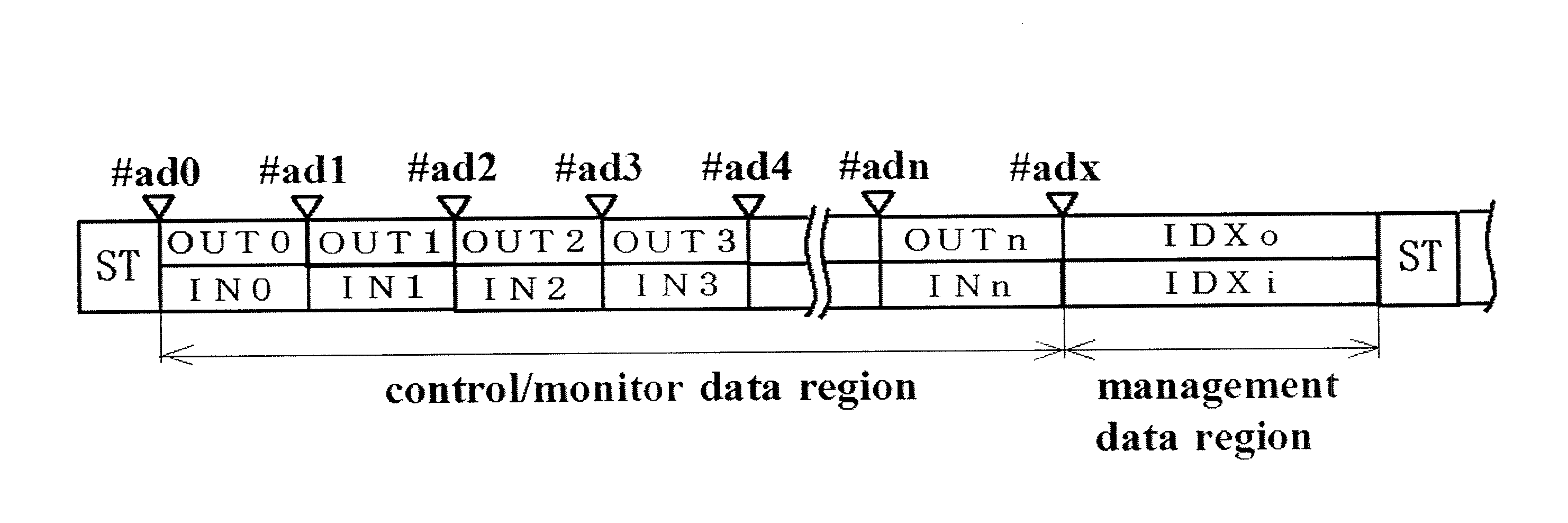
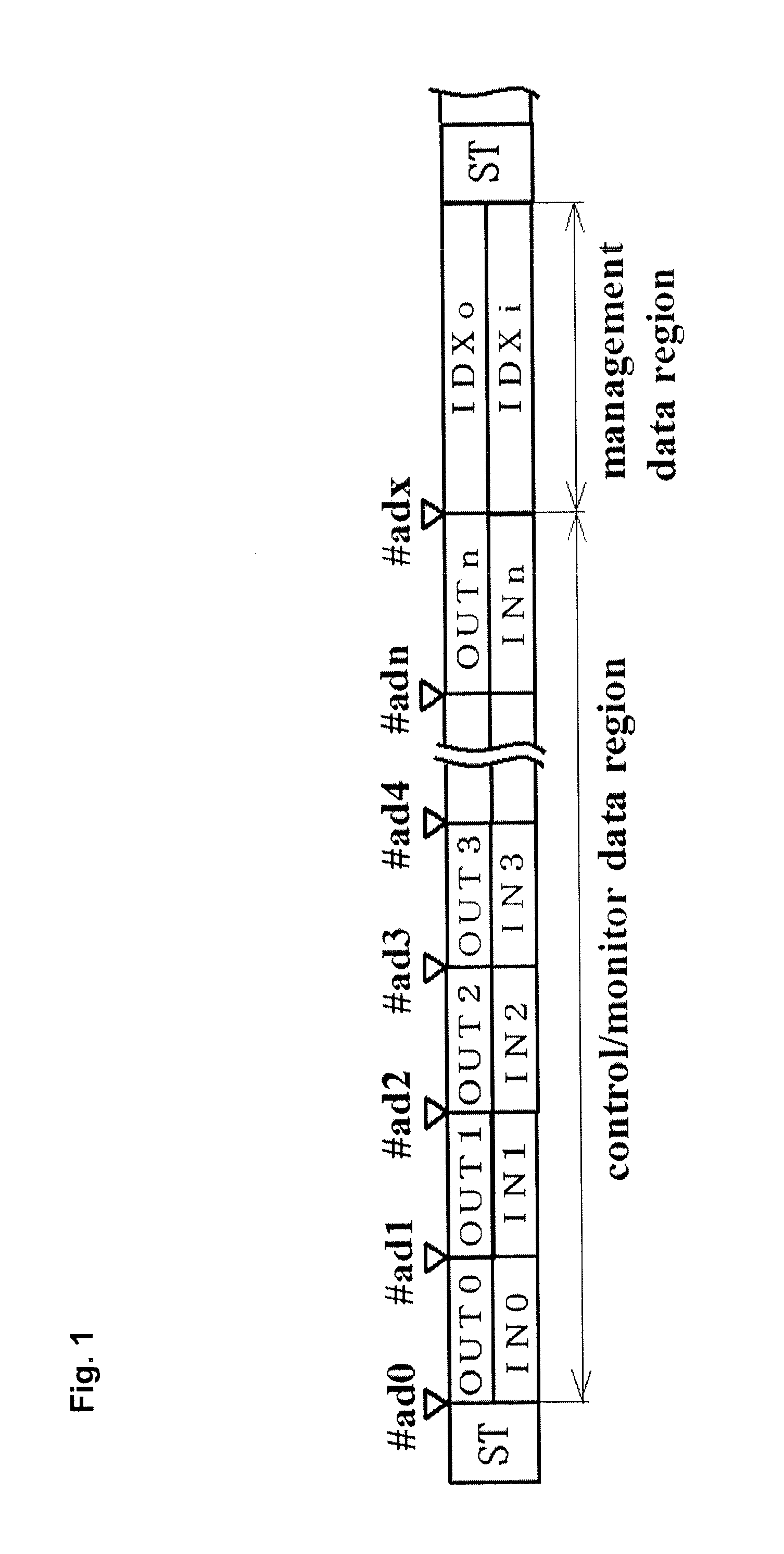
[0024]A description will be given of an embodiment of a control / monitor signal transmission system that employs a transmission line disconnection detection method according to the present invention, with reference to FIGS. 1 to 6.

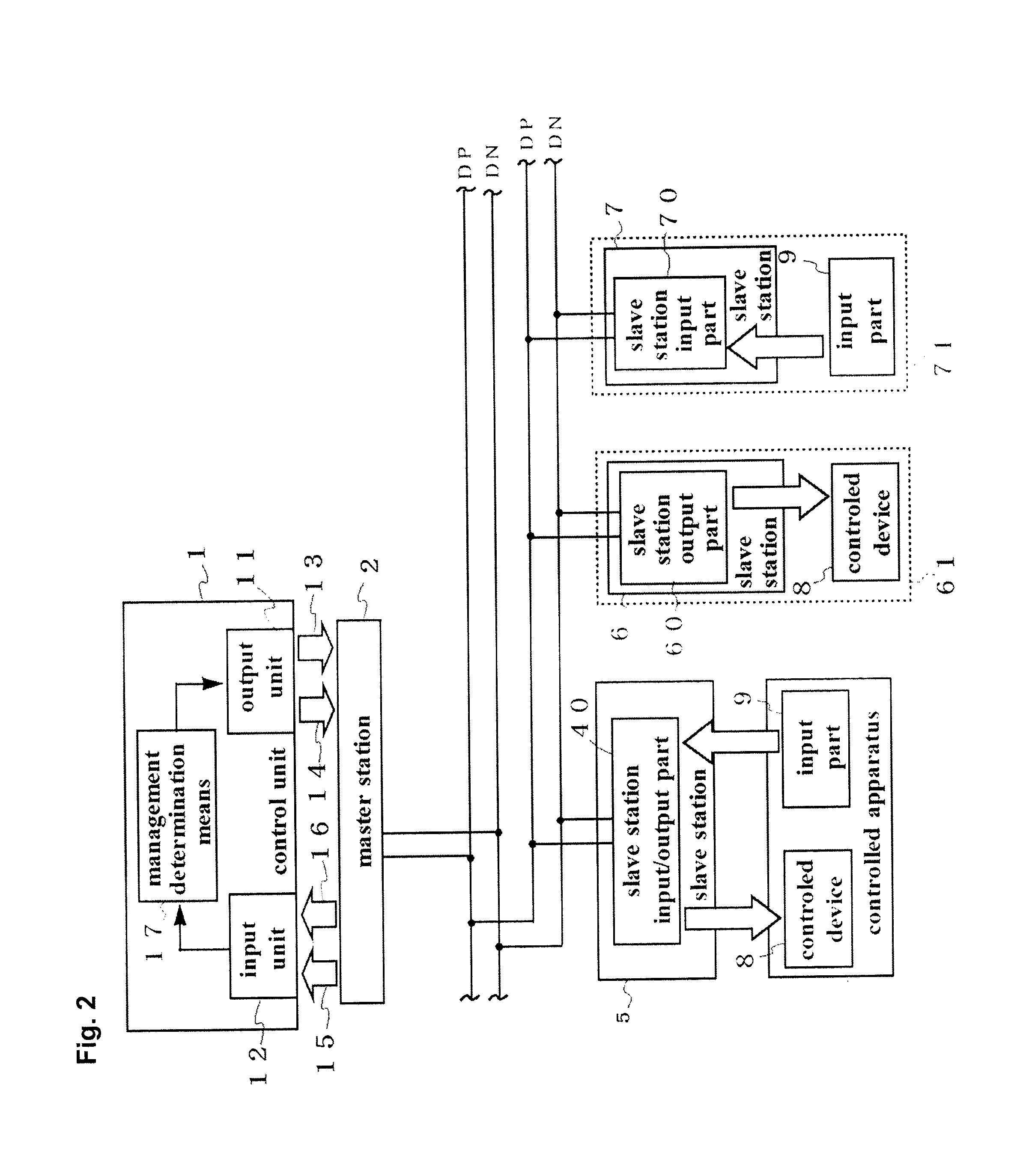
[0025]As depicted in FIG. 2, this control / monitor signal transmission system includes: a single master station 2 connected to a control unit 1 and common data signal lines DP and DN; and an input / output slave station 5, an output slave station 6 and an input slave station 7 that are connected to the common data signal lines DP and DN. It should be noted that for each of the individual slave stations, a single slave station is depicted in FIG. 2 for the sake of depiction's convenience, but there is no limitation on the types and number of slave stations connected to the common data signal lines DP and DN.

[0026]Each of the input / output slave station 5, the output slave station 6 and the input slave station 7 performs either of a signal output process and an i...


PUM


Abstract

A control/monitor signal transmission system that employs a transmission synchronization scheme in which a master station connected to a single control unit and a plurality of slave stations corresponding to a plurality of controlled apparatuses synchronize with each other through a transmission clock and data is transmitted therebetween over a common data signal line, a transmission line disconnection detection method that enables a disconnection of a transmission line to be detected precisely; and a slave station that is used for this method. A continuous pulse signal that the master station outputs to the common data signal line is provided with a management data region that includes a plurality of pulse signals and that differs from a control/monitor data region including data of a control data signal and data of a monitor data signal.

Description

TECHNICAL FIELD[0001]The present invention relates to a transmission line disconnection detection method for detecting a disconnection of a transmission line in a control / monitor signal transmission system, and a slave station used for the method, wherein the control / monitor signal transmission system decreases the number of signal lines between a master station connected to a single control unit and a plurality of slave stations corresponding to a plurality of controlled apparatuses, thereby connecting them with a common data signal line; and employs a transmission synchronization scheme in which the master station and the slave stations synchronize with each other through a transmission clock and data is transmitted therebetween over the common data signal line.BACKGROUND ART [0002]In a control system comprising a single control unit and a plurality of controlled apparatuses (including: a controlled part for operating in accordance with an instruction from the control unit; and a...

Claims


Application Information

Patent Timeline
IPC IPC(8): H04L12/26H04L69/40
CPCH04L43/0811H04B3/46
Inventor NISHIKIDO, KENJIHOSHI, YOUICHIITANI, KAZUO
Owner ANYWIRE
Why Eureka
Try Eureka