Fuel cell shutdown and startup using a cathode recycle loop

a fuel cell and recycle loop technology, applied in the direction of fuel cell details, fuel cell, electrochemical generators, etc., can solve the problems of reducing the life of the fuel cell, exacerbate the aforementioned corrosion of the catalyst and the catalyst support material, and limiting the effectiveness of certain modes of operation

a fuel cell and recycle loop technology, applied in the direction of fuel cell details, fuel cell, electrochemical generators, etc., can solve the problems of reducing the life of the fuel cell, exacerbate the aforementioned corrosion of the catalyst and the catalyst support material, and limiting the effectiveness of certain modes of operation

US20050058860A1Inactive Publication Date: 2005-03-17GM GLOBAL TECH OPERATIONS LLC

Image

  • Fuel cell shutdown and startup using a cathode recycle loop
  • Fuel cell shutdown and startup using a cathode recycle loop
  • Fuel cell shutdown and startup using a cathode recycle loop

Examples


Embodiment Construction

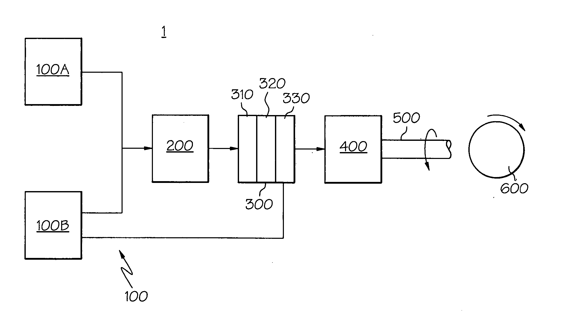
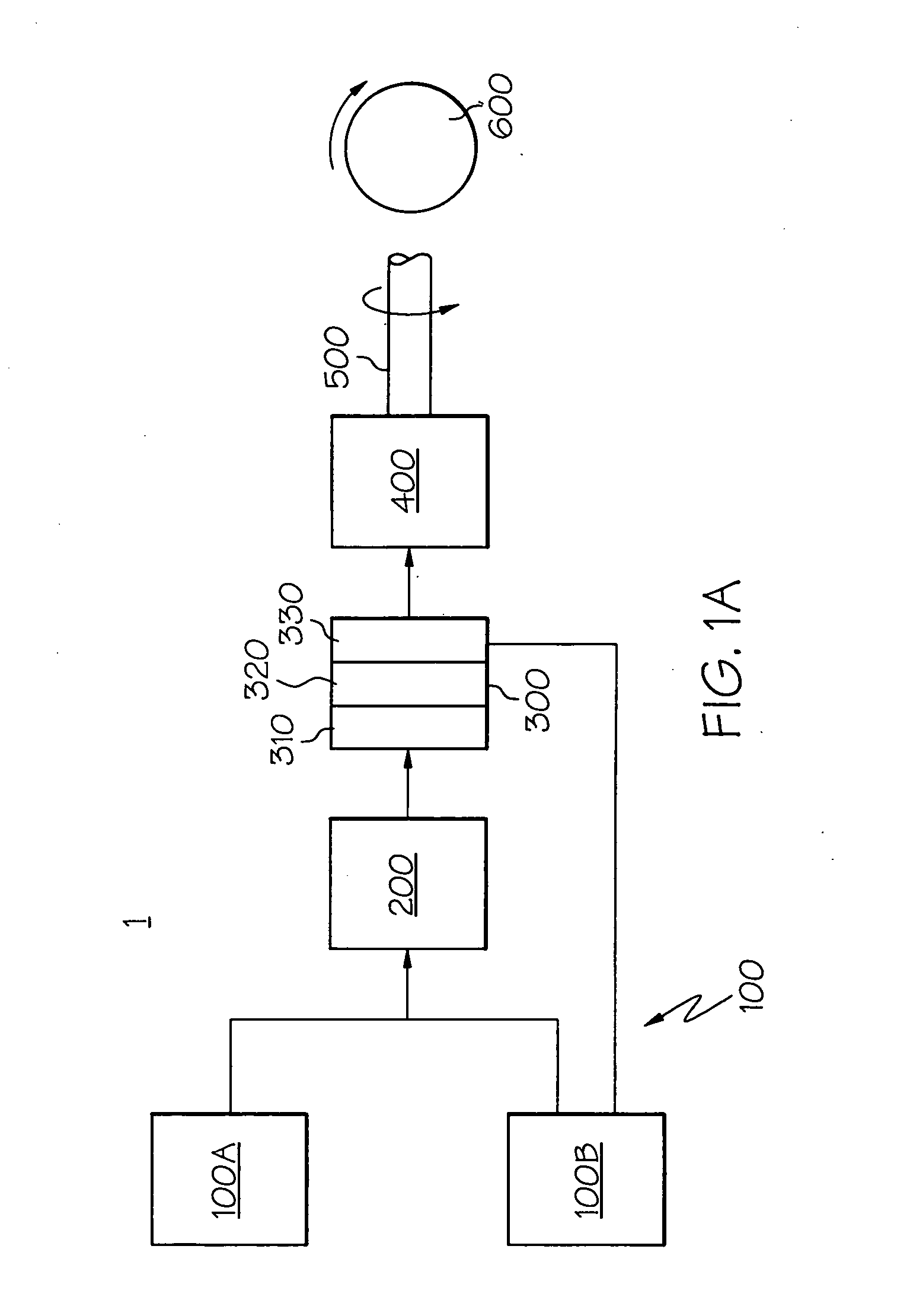
[0024] Referring initially to FIG. 1A, a block diagram highlights the major components of a mobile fuel cell system 1 according to the present invention. The system includes a fuel delivery system 100 (made up of fuel source 100A and oxygen source 100B), fuel processing system 200, fuel cell 300, one or more energy storage devices 400, a drivetrain 500 and one or more motive devices 600, shown notionally as a wheel. While the present system 1 is shown for mobile (such as vehicular) applications, it will be appreciated by those skilled in the art that the use of the fuel cell 300 and its ancillary equipment is equally applicable to stationary applications. It will also be appreciated by those skilled in the art that other fuel delivery and fuel processing systems are available. For example, there could be, in addition to a fuel source 100A and oxygen source 100B, a water source (not shown). Likewise, in some variants where substantially purified fuel is already available, the fuel pr...


PUM

PropertyMeasurementUnit
voltageaaaaaaaaaa
open circuit voltageaaaaaaaaaa

Abstract

A method and device for operating a fuel cell system. A recirculation loop coupled to a fuel cell cathode ensures that fluids passing through the cathode are recycled, thereby enabling reaction between residual oxygen in the recycled fluid and fuel that has been introduced into the recirculation loop until a reduced voltage level across the fuel cell is achieved. Attainment of the reduced voltage level indicates that the recycled fluid is substantially oxygen-free, yielding an inerting fluid. Thereafter, this compound, followed by air, or air directly can be used to purge the fuel cell's anode and related flowpath during system shutdown. Similarly during system startup, hydrogen can then be introduced into the fuel cell's anode and then air into the cathode and related flowpath for normal operation. The placement of a purge valve allows the anode to be purged with air without re-introducing air into the cathode.

Description

CROSS REFERENCE TO RELATED APPLICATIONS [0001] This application is a continuation in part of U.S. application Ser. No. 10 / 664,329, filed Sep. 17, 2003, and is related to commonly assigned U.S. patent application Ser. No. 10 / 739,463, filed Dec. 18, 2003, the entire disclosure of which is herein incorporated fully by reference.BACKGROUND OF THE INVENTION [0002] The present invention relates generally to operating a fuel cell system, and more particularly to starting up and shutting down a fuel cell in such a way as to minimize oxidation of catalyst support material while maintaining system simplicity. [0003] The use of catalysts to facilitate the electrochemical reaction between hydrogen and oxygen in fuel cells is well-known. Typically, the catalyst is in the form of a noble metal powder that is distributed on a support that is itself a powder of larger carbon or carbon-based particles. This powder-based approach allows for a significant increase in surface area upon which the aforem...

Claims


Application Information

Patent Timeline
17 Mar 2005
Publication
US20050058860A1
IPC
H01M8/00; H01M8/02; H01M8/04; H01M8/10
CPC
H01M8/04014; H01M8/04097; Y02E60/521; Y02E60/50; H01M8/04231; H01M8/04303; H01M8/04559
Inventors
GOEBEL, STEVEN G.