Riser pipe gas separator for well pump

a technology of riser pipe and separator, which is applied in the direction of fluid removal, earthwork drilling and mining, and wellbore/well accessories, etc., can solve the problems of not being able to locate a shroud intake below the perforation, and the motor could heat dramatically

Inactive Publication Date: 2005-08-23
BAKER HUGHES INC
View PDF19 Cites 58 Cited by
  • Summary
  • Abstract
  • Description
  • Claims
  • Application Information

AI Technical Summary

Benefits of technology

[0005]In this invention, a rotary pump is suspended in the well on a string of tubing. The pump has an intake for receiving well fluid and a discharge for discharging well fluid into the tubing. An electrical motor is coupled to the pump for rotating the pump. A barrier locates in the well below the intake of the pump and blocks well fluid from flowing below the barrier directly to the intake of the pump. A riser has an inlet in commun

Problems solved by technology

While a gas separator works well enough to separate gas prior to the entry in the pump, another problem exists, particularly in horizontal wells where slugging is a problem.
If large gas bubbles are encountered, the motor could heat drastic

Method used


Image

  • Riser pipe gas separator for well pump
  • Riser pipe gas separator for well pump
  • Riser pipe gas separator for well pump

Examples


Embodiment Construction

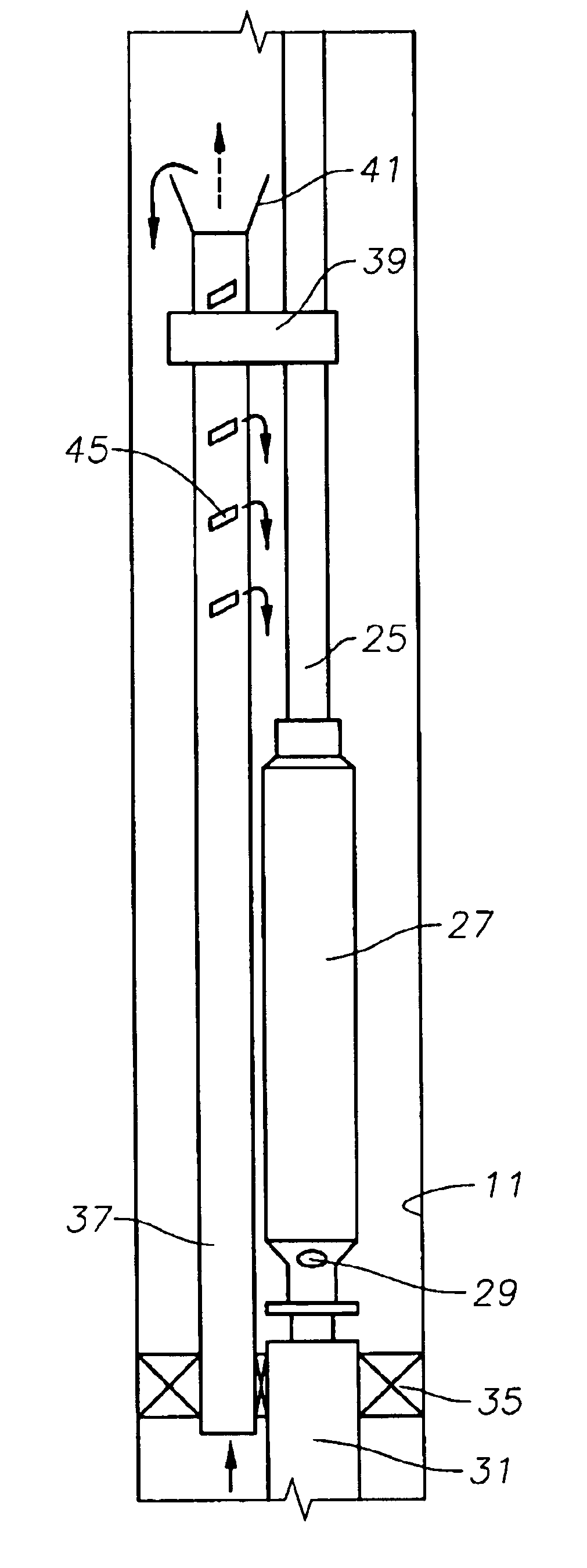
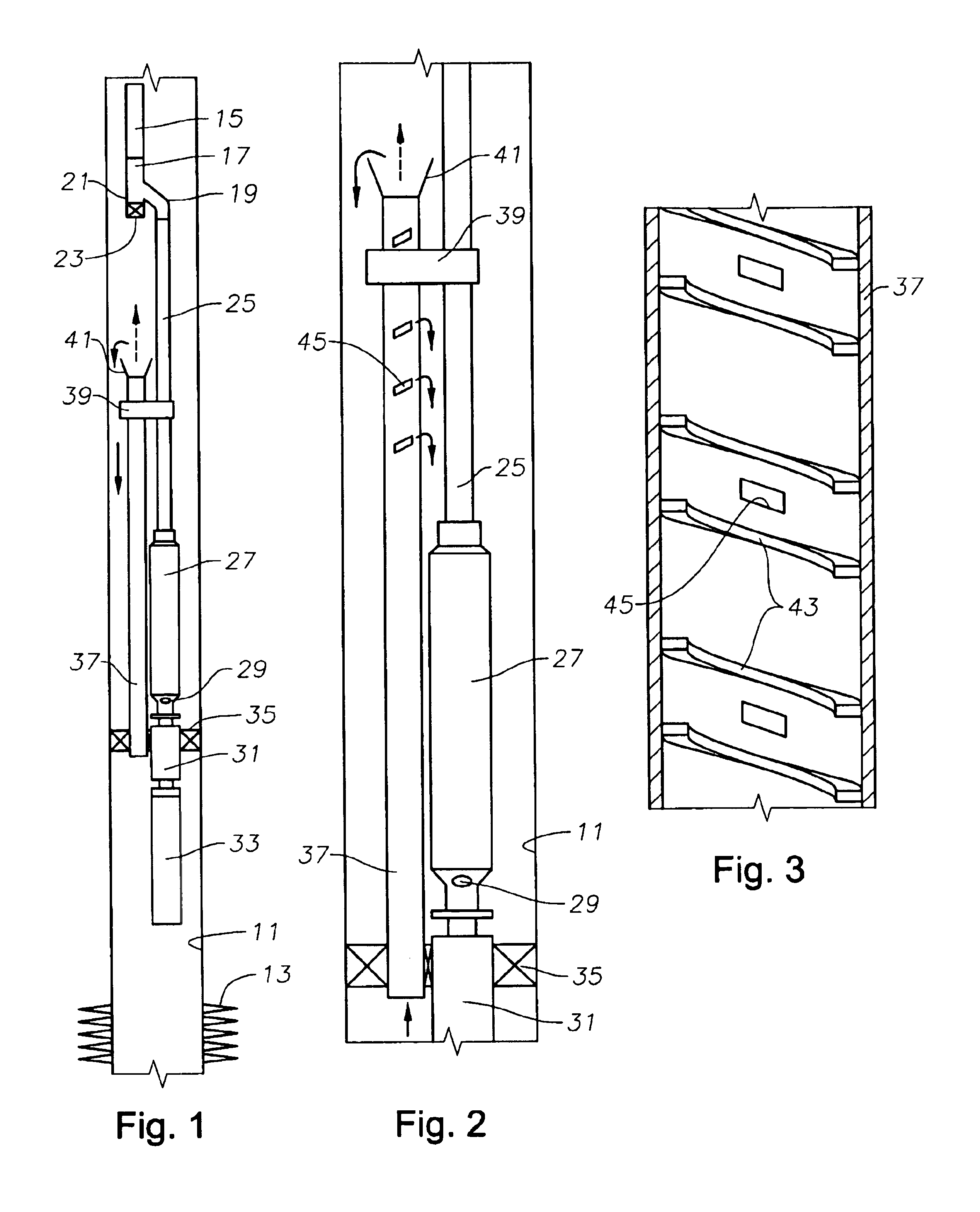
[0021]Referring to FIG. 1, the well has a casing 11 containing a set of perforations 13 to allow the flow of formation fluid into casing 11. A string of production tubing 15 extends into the well. In this embodiment, a Y-tube 17 is secured to the lower end of tubing 15. Y-tube 17 has a single upper end, an offset lower leg 19 and an axial lower leg 21. Axial leg 21 is located coaxial with the axis of tubing 15. Axial leg 21 extends only a short distance and contains a wireline profile for receiving a wireline plug 23.

[0022]Offset leg 19 secures to a discharge tube 25 that extends upward from a rotary pump 27. Pump 27 is shown in this example to be a centrifugal pump having a large number of stages, each stage having an impeller and diffuser. Alternately, rotary pump 27 could be a progressive cavity pump, which has an elastomeric stator with a double-helical cavity therein. A rotor having a helical configuration rotates within the stator. Pump 27 has an intake 29 on its lower end.

[00...


PUM


Abstract

A well pump has a riser gas separator for removing large slugs of gas prior to reentry into the pump. The riser extends upward from a barrier that is located in the well. The riser has an inlet that is located above an effective intake of the pump. Well fluid must turn to flow down to the pump, with gas separating by gravity flowing upward while the liquid flows downward. The downhole assembly has various configurations to assure that fluid flows past the motor for cooling.

Description

FIELD OF THE INVENTION[0001]This invention relates in general to submersible rotary well pump installations, and in particular to a riser pipe assembly for separating gas in the well fluid prior to entry in the pump intake.BACKGROUND OF THE INVENTION[0002]One category of well pump is an electrically driven rotary pump that is driven by a downhole electrical motor. These types of pumps operate best when pumping fluid that is primarily liquid. If the well fluid contains large quantities of gas, a gas separator can be connected to the pump assembly upstream of the pump for separating gas in the well fluid and discharging it into the casing. A common type of gas separator has rotatable vanes that separate the gas by centrifugal force.[0003]While a gas separator works well enough to separate gas prior to the entry in the pump, another problem exists, particularly in horizontal wells where slugging is a problem. The term “gas slugging” refers to large gas bubbles that are encountered and ...

Claims


Application Information

Patent Timeline
IPC IPC(8): E21B43/34E21B43/38
CPCE21B43/38
Inventor MURRAY, RICK G.FOX, MICHAEL J.WILSON, BROWN LYLEBROWN, DONN J.
Owner BAKER HUGHES INC
Why Eureka
Try Eureka