Packing case for cooling compressors and other machinery

a technology for compressors and packing cases, applied in the direction of sealing, liquid fuel engines, positive displacement liquid engines, etc., can solve the problems of increased heating in the clogged cup or cup, the heating of the packing cup,

Inactive Publication Date: 2005-08-23
HOERBIGER KOMPRESSORTECHNIK HLDG GMBH
View PDF18 Cites 44 Cited by
  • Summary
  • Abstract
  • Description
  • Claims
  • Application Information

AI Technical Summary

Benefits of technology

[0011]According to certain exemplary embodiments of the present invention, o-rings may be disposed between two packing cups or a packing cup and a flange where channels of each of the plurality of packing cups and the flange connect. A packing cup may have an annular shape and include an outer portion that is longer than an inner portion, forming an annular recess for receiving one or more seal rings or heat transfer rings. Channels in a packing cup may be located only within the outer portion of the packing cup.
[0012]A plurality of seal rings may be disposed around the surface of the shaft an...

Problems solved by technology

This friction causes heating of the packing cups.
This arrangement is called parallel flow and has the disadvantage that the passageways of one or mo...

Method used


Image

  • Packing case for cooling compressors and other machinery
  • Packing case for cooling compressors and other machinery
  • Packing case for cooling compressors and other machinery

Examples


Embodiment Construction

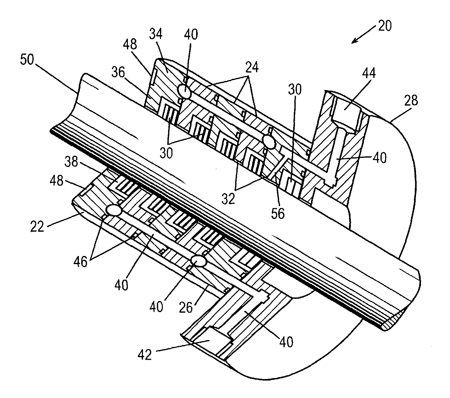
[0027]Referring now to the drawings, an exemplary embodiment of a packing case according to the present invention is shown in FIG. 1. A packing case 20 is disposed on a movable machinery shaft or piston rod 50, such as either a rotating shaft or a reciprocally movable piston rod of a conventional compressor. Packing case 20 includes a nose cup 22, a series of three cups 24, an end cup 26, and a flange 28. Cups 22, 24, and 26 and flange 28 may be constructed of steel, cast iron, bronze, or other suitable materials provided that the material meets the chemical resistance and mechanical strength requirements for a particular application, as well understood by those skilled in the art. Also understood by those skilled in the art is that the number of packing cups contained in any given packing case is a matter of conventional design choice. A packing case according to this invention may include a single packing cup designed in accordance with principles of this invention or a plurality ...


PUM


Abstract

A packing case for cooling compressors and other machinery is disclosed. A packing case includes an opening through which a movable machinery shaft may be inserted such that the packing case is mounted on the shaft. In an exemplary embodiment, the packing case contains at least one packing cup with channels through which a fluid coolant may flow. The channels form substantially parallel passageways along the length of the shaft that are spaced apart around the shaft circumference and series connected. The fluid coolant may be introduced through one or more inlet ports, circulate through the substantially parallel passageways of the at least one packing cup, and exit the packing case through one or more outlet ports. The fluid coolant may flow through the packing case in a single, continuous flow path or a split flow arrangement.

Description

FIELD OF THE INVENTION[0001]This invention relates generally to improvements in packing cases for cooling compressors and other machinery and more specifically to improvements in the coolant circulation structure of such cases.BACKGROUND OF THE INVENTION[0002]Generally, packing cases are used to provide a seal along and around a movable piston rod of a gas compressor to prevent the escape of gas from the piston cylinder along and around the surface of the piston rod. Packing cases are also used to provide gas tight seals along and around the movable shafts of other rotating machinery. A packing case member or packing cup is typically cylindrically shaped and contains a central circular opening for stationary mounting in a compressor housing on a reciprocally movable piston rod. The central opening has a slightly larger diameter than that of the piston rod preventing the piston rod from rubbing against the cup as the piston rod reciprocates. The series of cups forming the packing cas...

Claims


Application Information

Patent Timeline
IPC IPC(8): F16J15/16F16J15/26F04B39/00F04B39/06F04B53/16F16J15/44
CPCF04B39/00F04B39/0022F04B39/06F04B53/164F16J15/26F16J15/441Y10S277/93
Inventor MOWLL, WILLIAM L.
Owner HOERBIGER KOMPRESSORTECHNIK HLDG GMBH
Why Eureka
Try Eureka