LED-based elevated omnidirectional airfield light

a technology of airfield lights and led lights, which is applied in the field of airfield lighting, can solve the problems of high maintenance costs, low percentage of consumed energy converted into useful light, and inefficient conventional design

Inactive Publication Date: 2005-08-23
FARLIGHT
View PDF3 Cites 99 Cited by
  • Summary
  • Abstract
  • Description
  • Claims
  • Application Information

AI Technical Summary

Problems solved by technology

Unfortunately, this conventional design is very inefficient in that a low percentage of the consumed energy is converted into useful light.
Additionally, this conventional design results in high maintenance costs (e.g., the cost associated with relamping due to the relative low bulb lifetime of 1,000 hours).

Method used


Image

  • LED-based elevated omnidirectional airfield light
  • LED-based elevated omnidirectional airfield light
  • LED-based elevated omnidirectional airfield light

Examples


Embodiment Construction

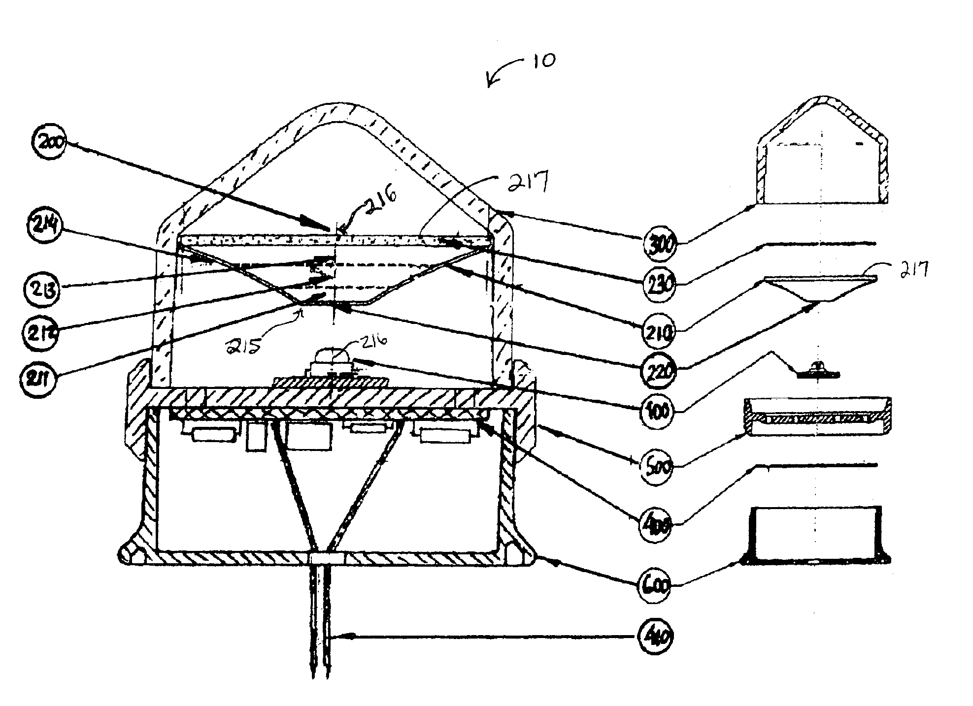
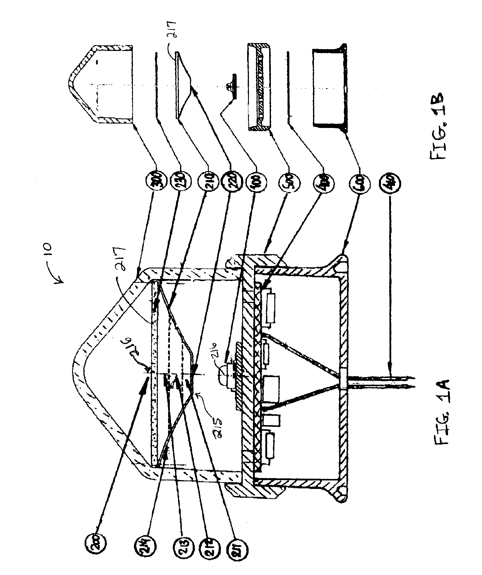
[0020]Referring now to FIG. 1, an elevated omnidirectional luminaire 10 includes a single LED 100, a light transformer 200, a hemispherical optical window 300, an electric / electronic circuit 400, a base 500, and an adapter 600.

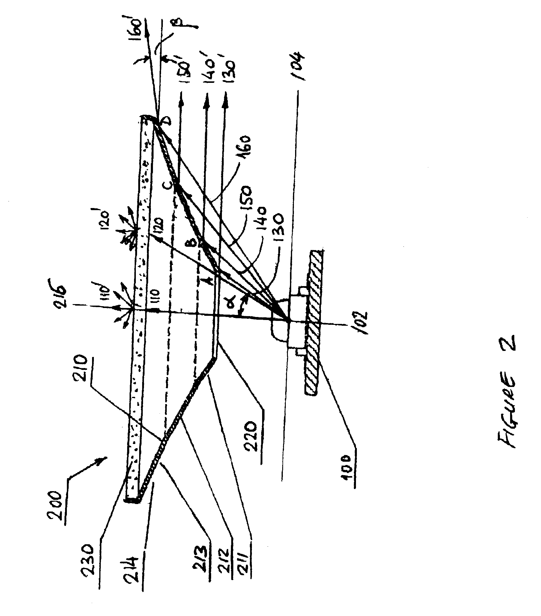
[0021]LED 100 emits light with a wide divergence, and light transformer 200 directs a significant portion of the light emitted by LED 100 in an omnidirectional pattern with a limited angle and a precalculated intensity distribution in the vertical plane, while the remaining emitted light is dispersed across the hemisphere.

[0022]Light transformer 200 is seated within hemispherical optical window 300 and transmits the light to the exterior of luminaire 10. Electric / electronic circuit 400 connects through an input 410 to an outside power source (not shown). Base 500 houses LED 100, optical window 300 and electric / electronic circuit 400 in a weatherproofed sealed arrangement. Adapter 600 is installed on a supporting structure (not shown).

[0023]Light transformer 20...


PUM


Abstract

A light emitting apparatus includes a light source, a light transformer, a hemispherical optical window, a circuit and a base. The light transformer includes a truncated hollow conical reflector, a curved reflective surface, and an optical element. The conical reflector has a truncated end facing the light source and a cone base opposite the truncated end. The conical reflector axis is coincident with a light source axis, and light passes through an opening on the truncated end. The curved reflective surface is between the truncated end and the cone base. The surface reflects light from the light source in a limited angle omnidirectional pattern with precalculated intensity distribution. The optical element is adjacent the cone base in a plane perpendicular to the conical reflector axis, and disperses the light passing through the truncated hollow cone reflector.

Description

CROSS-REFERENCE TO RELATED APPLICATIONS[0001]This application is a continuation-in-part application of U.S. Provisional Ser. No. 60 / 373,026 filed Apr. 16, 2002.BACKGROUND OF THE INVENTION[0002]1. Field of the Invention[0003]The present invention relates generally to illumination and airfield lighting. In particular, the present invention relates to runway and taxiway elevated edge lighting, heliport perimeter lighting, and the like.[0004]2. Discussion of the Related Art[0005]U.S. governmental and international specifications identify various requirements including spatial luminous intensity distribution, chromaticity, structural integrity, etc. For example, the Federal Aviation Administration Advisory Circular 150 / 53454-46B identifies the photometric specification for an elevated taxiway edge light (L-861T) as follows:[0006]Omnidirectional pattern in horizontal plane;[0007]2 candela average intensity between 0 and 6 degrees above horizon in vertical plane;[0008]0.2 candela intensity...

Claims


Application Information

Patent Timeline
Patent Type & Authority Patents(United States)
IPC IPC(8): B64F1/20B64F1/00F21V7/04F21V7/00F21S8/00
CPCB64F1/205F21V7/04F21S10/06F21V7/0008F21W2111/06F21Y2101/02Y10S362/80B64D2203/00F21Y2115/10
Inventor RIZKIN, ALEXANDERTUDHOPE, ROBERT H.
Owner FARLIGHT
Why Eureka
Try Eureka