Polyaxial modular skeletal hook

a technology of modular skeletal hooks and skeletons, applied in the field of orthopaedic surgery, can solve the problems of one-piece devices without adjustment capabilities of screws and hooks, and achieve the effect of positive attachment of devices to the bon

Inactive Publication Date: 2005-08-23
ATLAS SPINE
View PDF8 Cites 212 Cited by
  • Summary
  • Abstract
  • Description
  • Claims
  • Application Information

AI Technical Summary

Benefits of technology

[0012]It is a still further objective of the invention teach a set screw which has multiple functions of connecting the two...

Problems solved by technology

These screws and hooks are one piec...

Method used


Image

  • Polyaxial modular skeletal hook
  • Polyaxial modular skeletal hook

Examples


Embodiment Construction

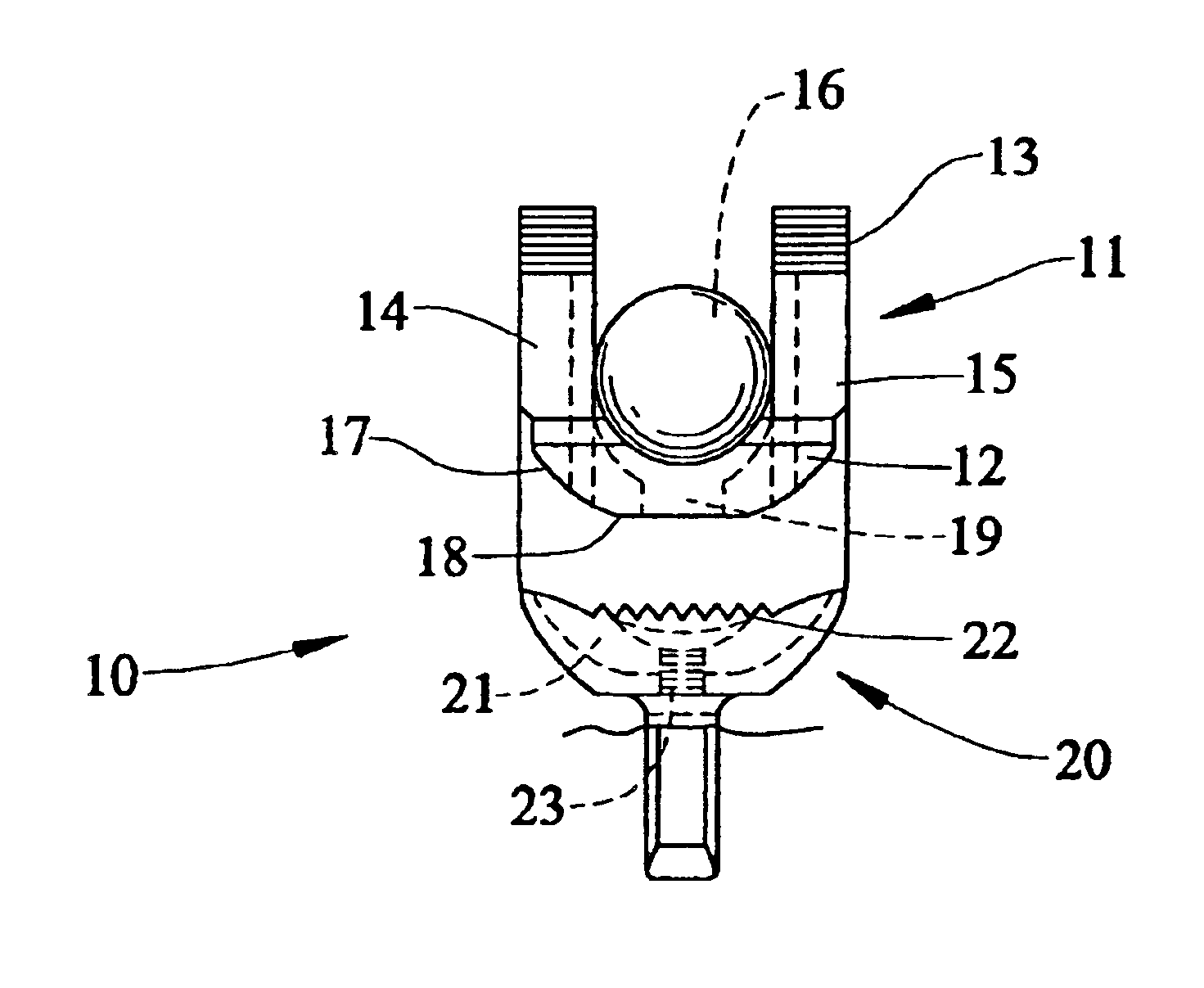
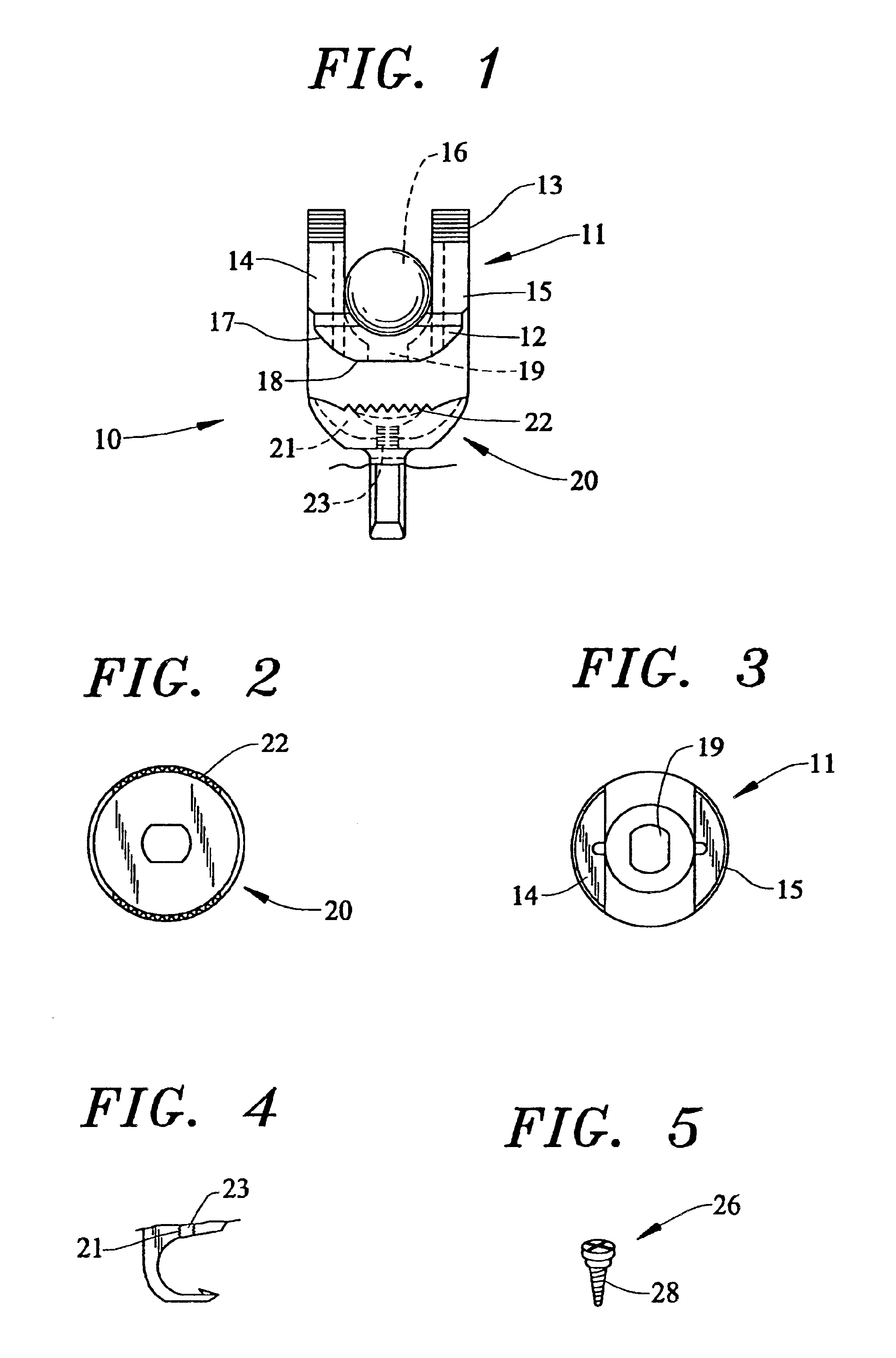
[0019]The modular polyaxial bone fixation device 10, shown in FIG. 1, has an upper module 11 formed with a U-shaped connector 12. The connector 12 has external threads 13 about the upstanding legs 14 and 15 for accepting a threaded nut (not shown) to connect bone support apparatus between the legs. A cross section of a spinal rod 16 is shown in phantom lines. The bottom portion of the U-shaped connector 12 is shaped as a portion of a ball 17 or nearly spherical, shown in FIG. 3. As shown, there is a flattened area 18. The bottom portion 17 also has an aperture 19 therethrough.

[0020]The attachment module 20 has a socket portion 21, shown in FIG. 2, shaped to accept the ball 17 of the connector module 11. The upper edge of the socket portion 21 has serrations 22 which act as stops for rotation when assembled. The socket portion has an aperture 23 extending through the thickened lower wall. The aperture has internal threads 27 to cooperate with the threads 28 of the set screw 26.

[0021]...


PUM


Abstract

A modular skeletal hook has an upper module for connecting with larger support apparatus to maintain bones of the skeleton in fixed relationship. The upper module is connected to an attachment module by a modified ball and socket arrangement. The attachment module has a C-shaped hook for engaging the bone. The angular orientation of the upper module and the attachment module may be fixed by a set screw threaded through the upper module and the attachment module.

Description

RELATED APPLICATIONS[0001]This application is a continuation of Provisional Application No. 60 / 353,215 filed Feb. 1, 2002.FIELD OF THE INVENTION[0002]This invention relates to the field of orthopedic surgery. Particularly, the invention is directed to skeletal fixation apparatus and implants having adjustable angular orientation between the bone attachment element and the rods or plates connected thereto.BACKGROUND OF THE INVENTION[0003]The purpose of the implant is to reinforce certain parts of the skeleton by use of strategically placed bone attachment devices. In some cases, these devices may support alignment support rods placed bilateral along the vertebrae as well as cross-link plates that bridge the spine.[0004]Conventionally, pedicle screws are use to attach the implants to the bone. However, there are instances in which it is not desirable or possible to use screws. Other attachment devices, such as hooks, may be used when it is not desirable to penetrate the bone. Usually,...

Claims


Application Information

Patent Timeline
IPC IPC(8): A61B17/70
CPCA61B17/7032A61B17/7056
Inventor BAYNHAM, BRET O'NEILBAYNHAM, MATTHEW G.
Owner ATLAS SPINE
Why Eureka
Try Eureka