
Pneumatic tire including slant main grooves and sipes

a technology of pneumatic tires and sipes, which is applied in the field of pneumatic tires, can solve the problems of uneven wear resistance reduction, difficulty in achieving both drainage performance and uneven wear resistance, and achieve the effects of high drainage effect, improved even wear resistance, and high drainage performan

Inactive Publication Date: 2005-08-30
THE YOKOHAMA RUBBER CO LTD
View PDF8 Cites 6 Cited by
  • Summary
  • Abstract
  • Description
  • Claims
  • Application Information

AI Technical Summary

Benefits of technology

The present invention provides a pneumatic tire with a block pattern that combines both drainage performance and uneven wear resistance. The tire includes a straight main groove, lateral grooves, and slant main grooves. The slant main grooves cross three or more lateral grooves and are inclined relative to the tire circumferential direction. The groove width of the center portion of each slant main groove is wider than that of the straight main groove, which improves uneven wear resistance. The inclination angle of the slant main grooves is set in a range of 10 to 45 degrees, and the maximum groove width is set to be 80 to 1 10% of the groove width of the straight main groove. This results in a more uniform contact pressure distribution and improved uneven wear resistance. The slant main grooves exhibit a high drainage effect during turning and secure high drainage performance during straight running in cooperation with the straight main groove. The invention achieves both drainage performance and uneven wear resistance.

Problems solved by technology

However, when the slant groove sections 13a are disposed as described above, a contact pressure distribution of each block 14 defined by the straight main grooves 12 and the lateral grooves 13 results in non-uniform, causing a reduction in uneven wear resistance.
Thus, in terms of the pneumatic tire having a block pattern defined by straight grooves and slant grooves, there has been a difficulty in achieving both drainage performance and uneven wear resistance.

Method used


Image

  • Pneumatic tire including slant main grooves and sipes
  • Pneumatic tire including slant main grooves and sipes
  • Pneumatic tire including slant main grooves and sipes

Examples


example

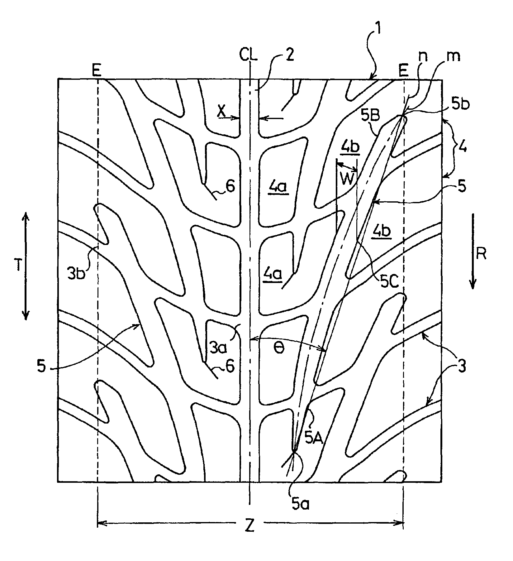
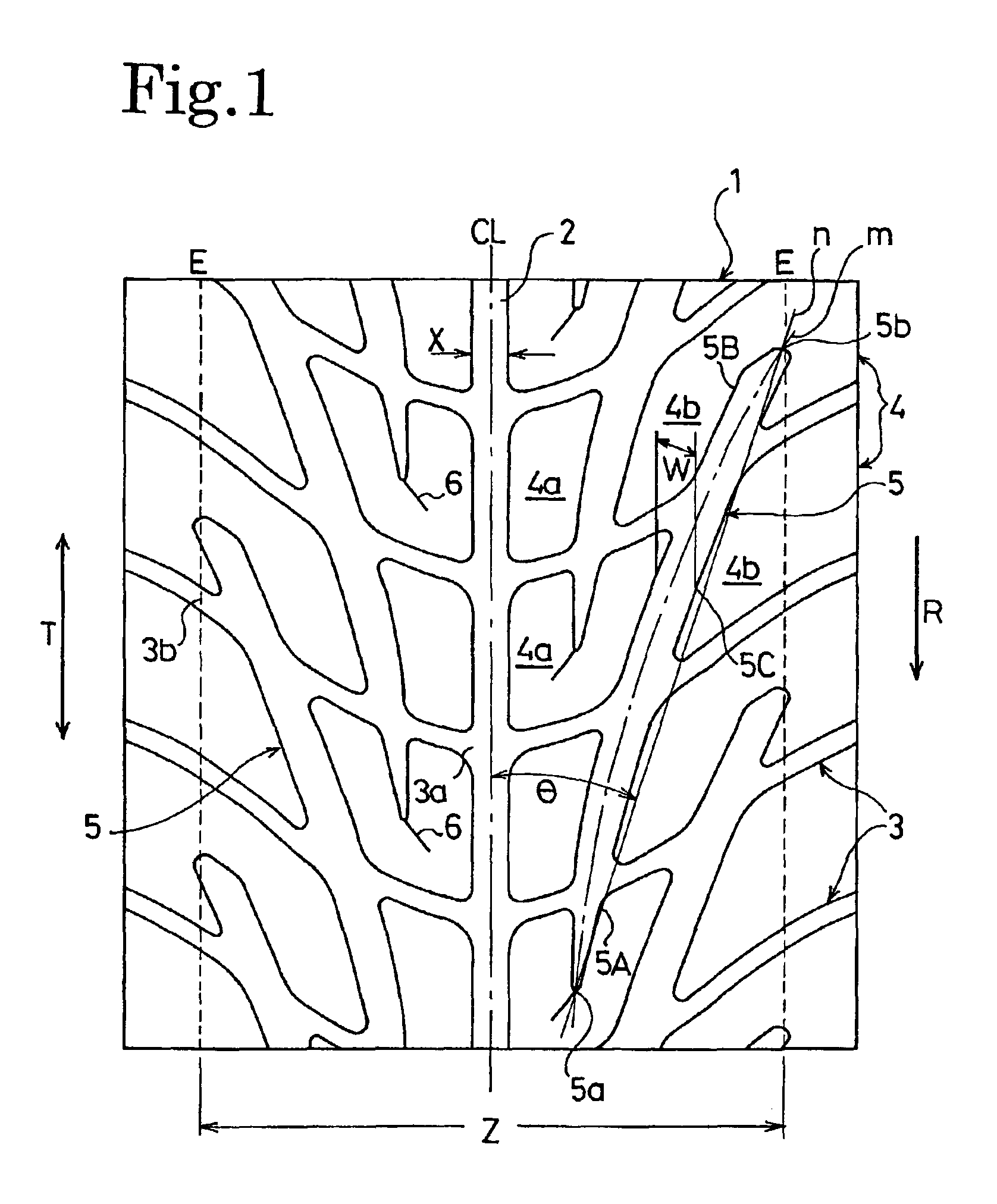
[0025]Tires 1 to 7 concerning to the present invention, comparative tires 1 to 7, and conventional tires were prepared with the same tire size of 215 / 45R17, the present invention tires 1 to 6 and the comparative tires 1 to 4, with the structure of FIG. 1, having the inclination angles and maximum groove widths of the slant main grooves shown in Table 1, the present invention tire 7 having the same structure as the present invention tire 2 except that the slant main grooves were formed in straight, the comparative tire 5 having the same structure as the present invention tire 2 except that each of the slant main grooves was arranged to cross two lateral grooves, the comparative tire 6 having the same structure as the present invention tire 2 except that the slant main grooves were communicatingly connected at both ends thereof to the lateral grooves, the comparative tire 7 having the same structure as the present invention tire 2 except that the slant main grooves had a constant groo...


PUM


Abstract

A pneumatic tire according to the present invention includes a tread surface having a tire rotation direction designated in one direction. The tread surface has a straight main groove extending in a circumferential direction of the tire in the center, and lateral grooves obliquely extending in a width direction of the tire on both sides thereof, defining blocks thereon. On both sides of the straight main groove, left and right slant main grooves are arranged to cross three or more lateral grooves. Both ends of-the slant main grooves are positioned within the blocks, and the groove width thereof is gradually enlarged from both end portions toward the center portion of the slant main groove. The inclination angle of the slant main grooves relative to the tire circumferential direction is set in a range of 10 to 45°, and the maximum groove width thereof is set to 80 to 110% of the groove width of the straight main groove.

Description

BACKGROUND OF THE INVENTION[0001]The present invention relates to a pneumatic tire and, more specifically, to a pneumatic tire capable of compatibly achieving both drainage performance and uneven wear resistance.[0002]In general, it has been known that a straight groove extending on the tread surface of a pneumatic tire in a circumferential direction of the tire can provide a drainage effect during straight running, and a slant groove extending obliquely relative to the tire circumferential direction thereon can provide high drainage during turning. Thus, conventionally, in order to secure high drainage performance during both straight running and turning, a tread pattern combining the straight groove or grooves with the slant grooves has been proposed.[0003]An example is illustrated in FIG. 2. Three straight main grooves 12 are disposed on a tread surface 11 extending in a tire circumferential direction T and drainage is secured during straight running by these three straight main ...

Claims


Application Information

Patent Timeline
Patent Type & Authority Patents(United States)
IPC IPC(8): B60C11/12B60C11/03B60C11/04B60C11/11
CPCB60C11/0302B60C11/12Y10S152/03B60C11/03
Inventor MASAKI, TAKEO
Owner THE YOKOHAMA RUBBER CO LTD
Learn More