
System and Method for Sizing, Inserting and Securing Artificial Disc in Intervertebral Space

a technology of intervertebral space and artificial disc, which is applied in the field of system and method for sizing, inserting and securing artificial discs in intervertebral space, can solve the problems of limited mobility, common joint degeneration, and limited success of conservative treatments, and achieves exceptional mechanical performance and biocompatibility characteristics

Inactive Publication Date: 2008-05-01
PIONEER SURGICAL TECH INC
View PDF58 Cites 88 Cited by
  • Summary
  • Abstract
  • Description
  • Claims
  • Application Information

AI Technical Summary

Benefits of technology

[0010] Testing in our laboratories however, told a different and unexpected story. In simulated weight bearing artificial joint configurations, PEEK against PEEK performed very favorably. PEEK articulating against PEEK demonstrated exceptional mechanical performance and biocompatibility characteristics required for load bearing artificial joints used in the human body and in other animals. PEEK may also be manufactured in a fiber reinforced form, typically carbon fiber, which also performs favorably against itself and against non-fiber reinforced PEEK.
[0011] Once PEEK was recognized as a viable option for self articulation, it became clear that an entire articulating joint could be made from the material without the need for metallic structural or articulating components. This discovery substantially simplified the nature of weight bearing artificial joint replacement design and great benefits have emerged. A partial list of these benefits include artificial joints that; have less components due to integrating features into the same component that were previously separated due to the need for a plurality of materials to serve the function, will last longer due to favorable wear characteristics, are substantially radiolucent, have a modulus of elasticity closer to the bone tissue they are implanted in, and are ultimately less expensive. It is important to note that less components typically equates to fewer modes of failure, reduced inventory, and simplified manufacturing and assembly. Although less preferred, clearly one may choose to keep the metallic components of an implant system and utilize PEEK on each articulating surface of the artificial joint for a PEEK on PEEK articulation.
[0013] For example, there is a need for a simplified radiolucent artificial disc device, with excellent wear characteristics and features that will secure the device to the vertebral endplates or otherwise restrain it between the vertebral bodies. An artificial disc such as this would be particularly useful as a lumbar disc replacement, and even more so as a cervical disc replacement. The cervical disc is much smaller than the lumbar disc as is the space the cervical disc occupies. For at least this reason, a simplified design utilizing fewer parts is beneficial.
[0018] Generally, the various systems and methods described herein allow for an implant, such as an artificial disc, to be properly sized, implanted and secured in an intervertebral space with the disc having a bearing interface that preserves motion between the upper and lower vertebrae between which the disc is implanted and secured. In each form described herein, a trial spacer is not only used to assess the size of the intervertebral space so that an appropriately sized disc implant can be selected, it is also used to assist in generating features in the vertebrae and / or end plates thereof (hereinafter “vertebral bodies”) for a securing mechanism that holds and retains the disc implant in the intervertebral space.
[0022] In addition, securing mechanisms according to the present invention may incorporate designs that transmit tactile feedback to the surgeon when the securing mechanism is being operated. As it is very difficult for the surgeon to visually ascertain the position of the implant and its securing features during operation, a surgeon will also use his hands to feel for tactile responses transmitted from the implant and through his tools. In one embodiment, the securing mechanism has a cammed surface for interacting with a corresponding cammed surface to cause the securing mechanism to be biased against the implant to provide resistance against the movement of the securing mechanism that can be felt through the surgeon's tools. In this manner, the surgeon can easily ascertain when the securing mechanism has been fully extended or deployed. The tactile feedback features of the securing mechanism also prevent the securing mechanism from being over- or under-actuated, i.e. deploying the securing mechanism beyond its intended range of motion, or failing to fully deploy the securing mechanism. This condition may result in improper fixation of the implant and cause damage to the implant, spine, nerves, vascular system, or other tissue in the area around the spine.

Problems solved by technology

Joint degeneration is a common problem that can occur in a variety of joints throughout the human body.
These conservative treatments sometimes meet only limited success.
If unsuccessful, the patient typically will continue to experience ongoing pain and limited mobility.
However, spinal fusion has proved to cause an increase in degeneration at other vertebral levels that must compensate for the loss of motion at the fused level commonly causing the patient to relapse into more pain and limited mobility.
Metal on metal implants have a history of failure in long term use, however, precision machining has spawned a reemergence of implants using these materials since it is believed that this change in manufacturing greatly improves the wear.
Regardless, the metal implants are radiopaque and continue to frustrate surgeons due to the difficulty in imaging the affected area.
Other implants, such as those using a polymer or elastomeric core between metallic plates suffer from the same radiopaque frustrations due to the metal components in addition to the added complexities of design due to the necessity of utilizing a multitude of materials for a single implant.
The prior art discloses a laundry list of biocompatible materials including metals, ceramics, and polymers, that can be used for the manufacture of these implants, yet historically many of these materials have failed when interfaced together and tested in an articulating joint.
There is in particular an extensive history of failure when polymers articulate against polymers in weight bearing artificial joints.
However, the prior art has been careful not to suggest self-articulating PEEK on PEEK as a suitable material combination in weight bearing joint replacement devices due to the failure history of biocompatible polymers articulating against themselves.

Method used


Image

  • System and Method for Sizing, Inserting and Securing Artificial Disc in Intervertebral Space
  • System and Method for Sizing, Inserting and Securing Artificial Disc in Intervertebral Space
  • System and Method for Sizing, Inserting and Securing Artificial Disc in Intervertebral Space

Examples


Embodiment Construction

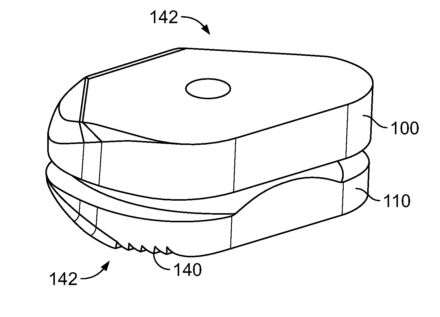
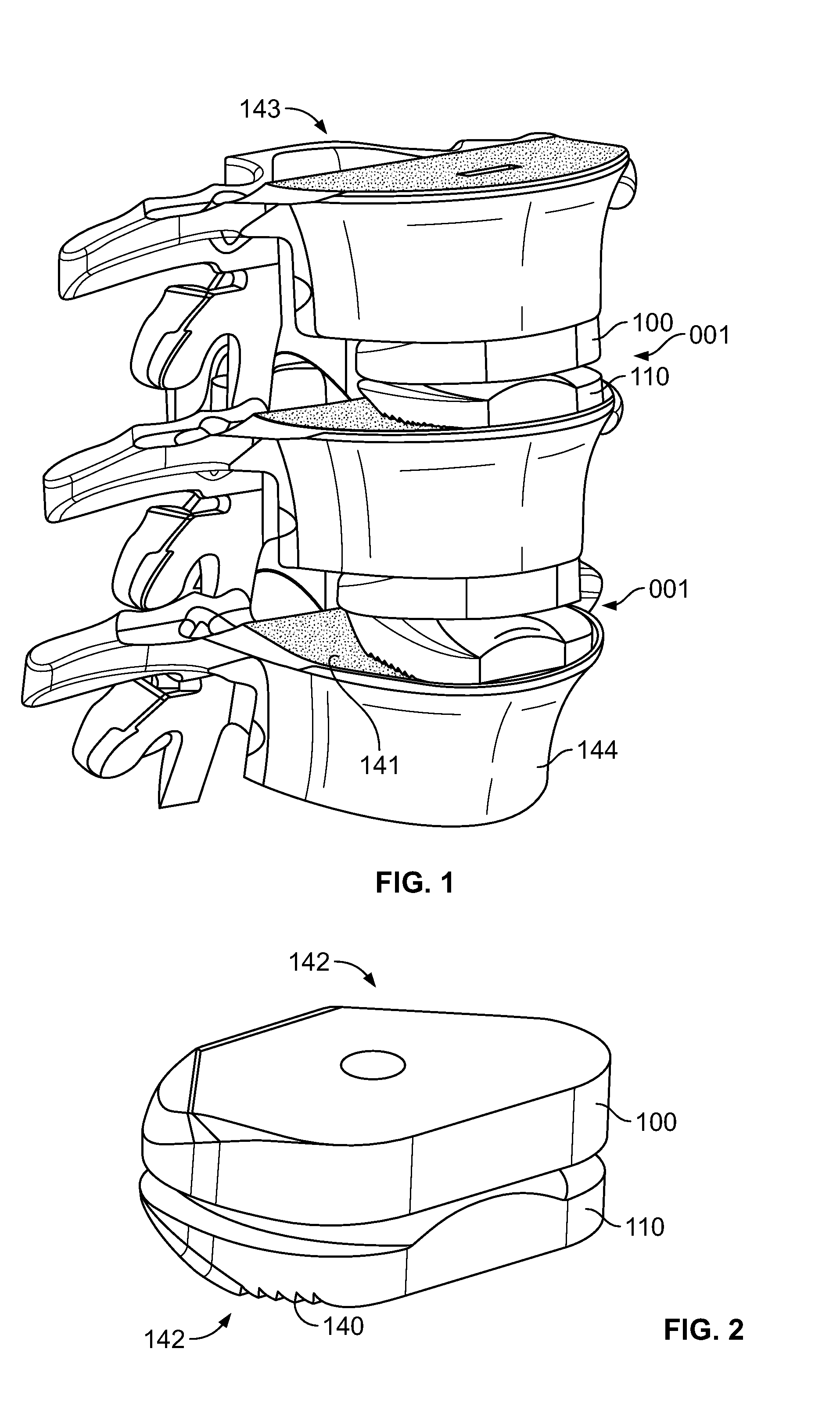
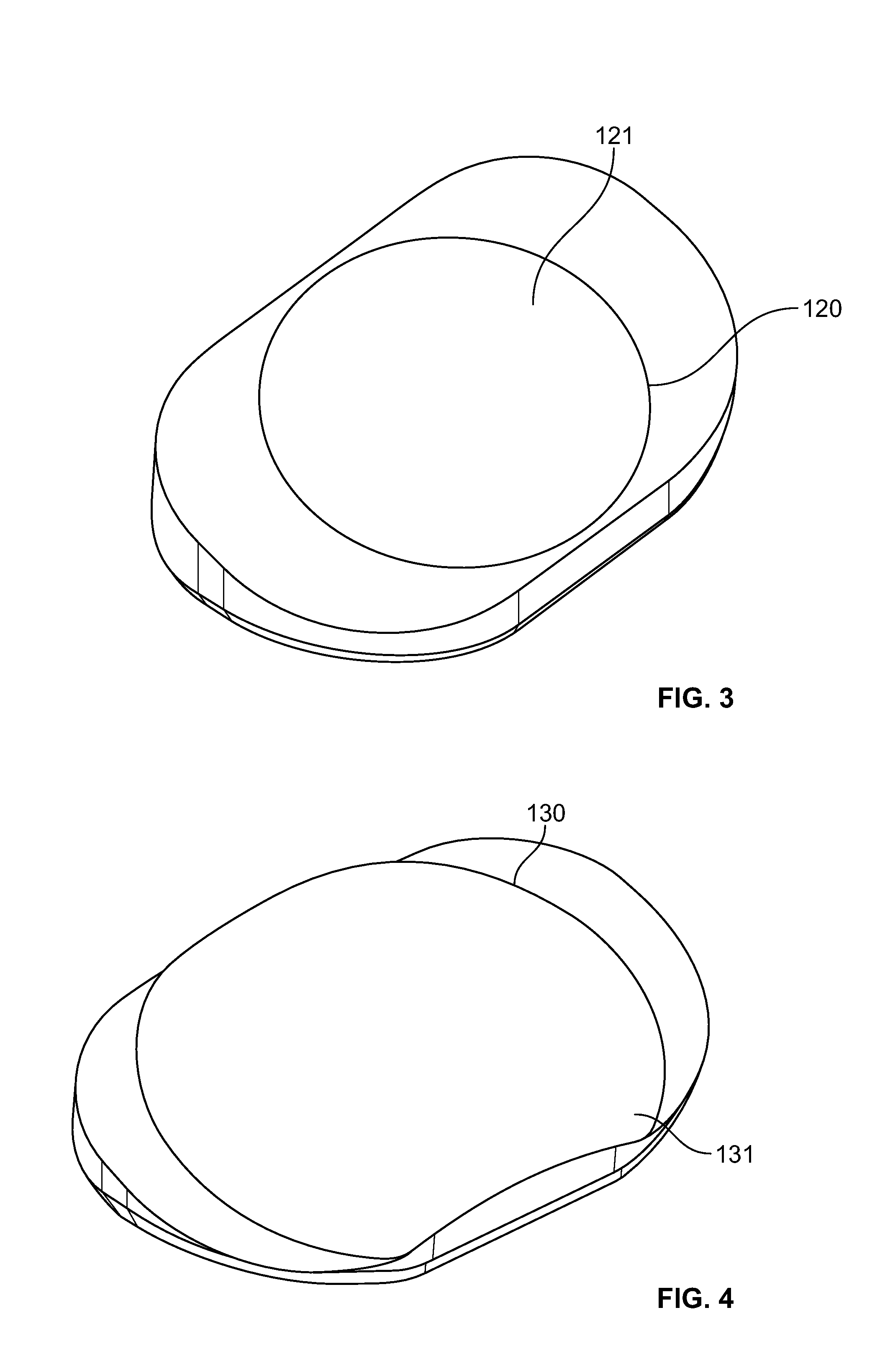
[0140] In a preferred embodiment, such as illustrated in FIGS. 1-4, an artificial disc device 001 comprises an upper shell 100 and lower shell 110. The upper shell 100 comprises a substantially concave recess portion 120, and the lower shell 110 comprises a substantially convex portion 130. Although not preferred, the concave and convex portions may be switched such that the upper shell 100 may alternatively comprise the convex portion 130.

[0141] The convex portion 130 comprises a convex articulation surface 131, and the concave portion 120 comprises a concave articulation surface 121. It is preferred that the articulation surfaces 121 and 131 have substantially matching geometries or radiuses of curvature although some mismatch of curvature may be desired to provide a combination of rolling and sliding motion to occur between the articulation surfaces 120 and 121. The geometries may be complex in nature but preferably are ball and socket style. The convex portion 130 and concave p...


PUM

PropertyMeasurementUnit
angleaaaaaaaaaa
resistanceaaaaaaaaaa
elastic deformationaaaaaaaaaa

Abstract

A prosthetic spinal implant having a deployable securing mechanism that is deployable into a portion of the vertebral space for affixing the implant between the vertebrae, the securing mechanism having tactile feedback means comprising a surface for transmitting tactile feedback during deployment of the securing mechanism. A spinal implant having deployable securing means that interface with the implant to prevent the deployable securing means from retracting after deployment. An implant that utilizes its resilient properties to provide the user with tactile feedback with which the user may ascertain the position of the securing mechanism. A system and tools for sizing and implanting implants with the aforementioned characteristics.

Description

RELATED APPLICATIONS [0001] This application is related to Provisional Application No. 60 / 825,865, filed Sep. 15, 2006, and Provisional Application No. 60 / 912,138, filed Apr. 16, 2007, both of which are also incorporated herein by reference in their entirety.FIELD OF THE INVENTION [0002] The invention relates to systems and methods for sizing an intervertebral space and placement of an appropriately sized implant therein and, more particularly, to systems and methods for sizing, inserting and securing an implant in the intervertebral space. BACKGROUND OF THE INVENTION [0003] Joint degeneration is a common problem that can occur in a variety of joints throughout the human body. The condition typically is more prevalent as the skeletal system ages and is often treated with medications and / or physical therapy. These conservative treatments sometimes meet only limited success. If unsuccessful, the patient typically will continue to experience ongoing pain and limited mobility. [0004] Of...

Claims


Application Information

Patent Timeline
Patent Type & Authority Applications(United States)
IPC IPC(8): A61F2/44A61B17/56
CPCA61B17/1671A61F2310/00796A61B17/86A61F2/44A61F2/4425A61F2/4611A61F2/4684A61F2002/30112A61F2002/30383A61F2002/30387A61F2002/305A61F2002/30571A61F2002/30578A61F2002/30579A61F2002/30601A61F2002/30662A61F2002/30823A61F2002/30884A61F2002/30894A61F2002/30899A61F2002/30904A61F2002/449A61F2002/4627A61F2002/4628A61F2220/0025A61F2230/0004A61B17/1757
Inventor TRUDEAU, JEFFREY L.JANOWSKI, BRIAN PATRICKKILPELA, THOMASBROWN, TIMJACKSON, MICHAEL R.BAO, QI-BIN
Owner PIONEER SURGICAL TECH INC
Learn More