Fluid storage and dispensing system featuring interiorly disposed and exteriorly adjustable regulator for high flow dispensing of gas

a technology of fluid storage and gas, which is applied in the direction of liquid transferring device, container discharge method, transportation and packaging, etc., can solve the problems of inability to monitor the pressure in the storage and dispensing vessel, difficult to determine or predict in advance when the vessel will be empty, and compromised the safety of the fluid storage and dispensing system

Inactive Publication Date: 2001-07-10
ENTEGRIS INC
View PDF6 Cites 89 Cited by
  • Summary
  • Abstract
  • Description
  • Claims
  • Application Information

AI Technical Summary

Benefits of technology

to provide a fluid storage and dispensing system comprising a storage and dispensing system with a regulator device interiorly positioned in the vessel, in which the amount of the fluid in the vessel is readily determinable.

Problems solved by technology

This is disadvantageous, since the SPR is typically set for sub-atmospheric pressure release of gas, in order to maximize the safety of the fluid storage and dispensing system.
If the SPR is set at super-atmospheric pressure and then installed in the vessel, the safety of the fluid storage and dispensing system is compromised by the super-atmospheric pressure set point during transport and storage of the system, as well as during off-line (stand-by) periods in the process facility.
Another deficiency of the prior fluid storage and dispensing system is that it is not able to monitor pressure in the storage and dispensing vessel.
As a result, it is difficult to determine or predict in advance when the vessel will be empty.

Method used


Image

  • Fluid storage and dispensing system featuring interiorly disposed and exteriorly adjustable regulator for high flow dispensing of gas
  • Fluid storage and dispensing system featuring interiorly disposed and exteriorly adjustable regulator for high flow dispensing of gas
  • Fluid storage and dispensing system featuring interiorly disposed and exteriorly adjustable regulator for high flow dispensing of gas

Examples


third embodiment

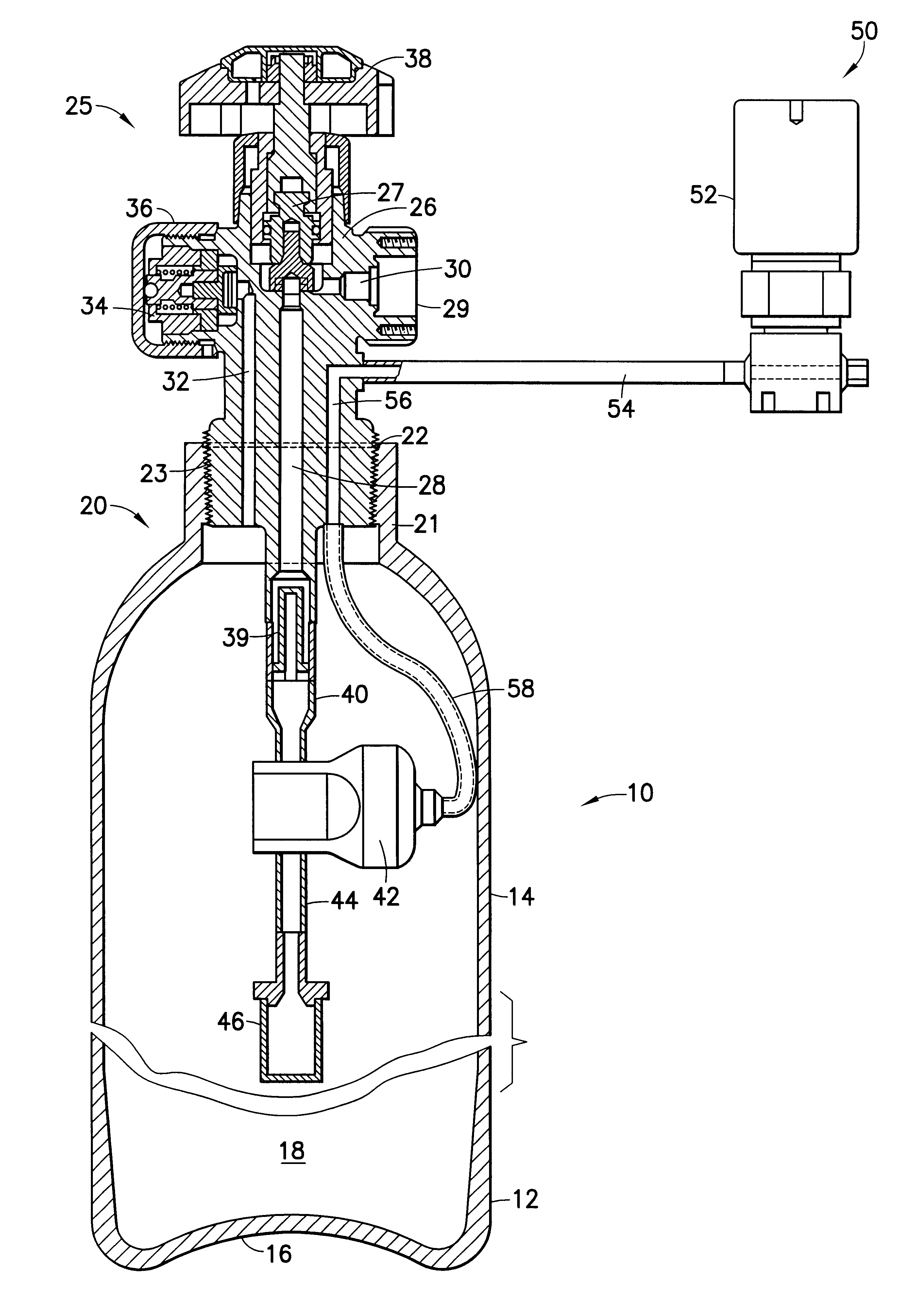
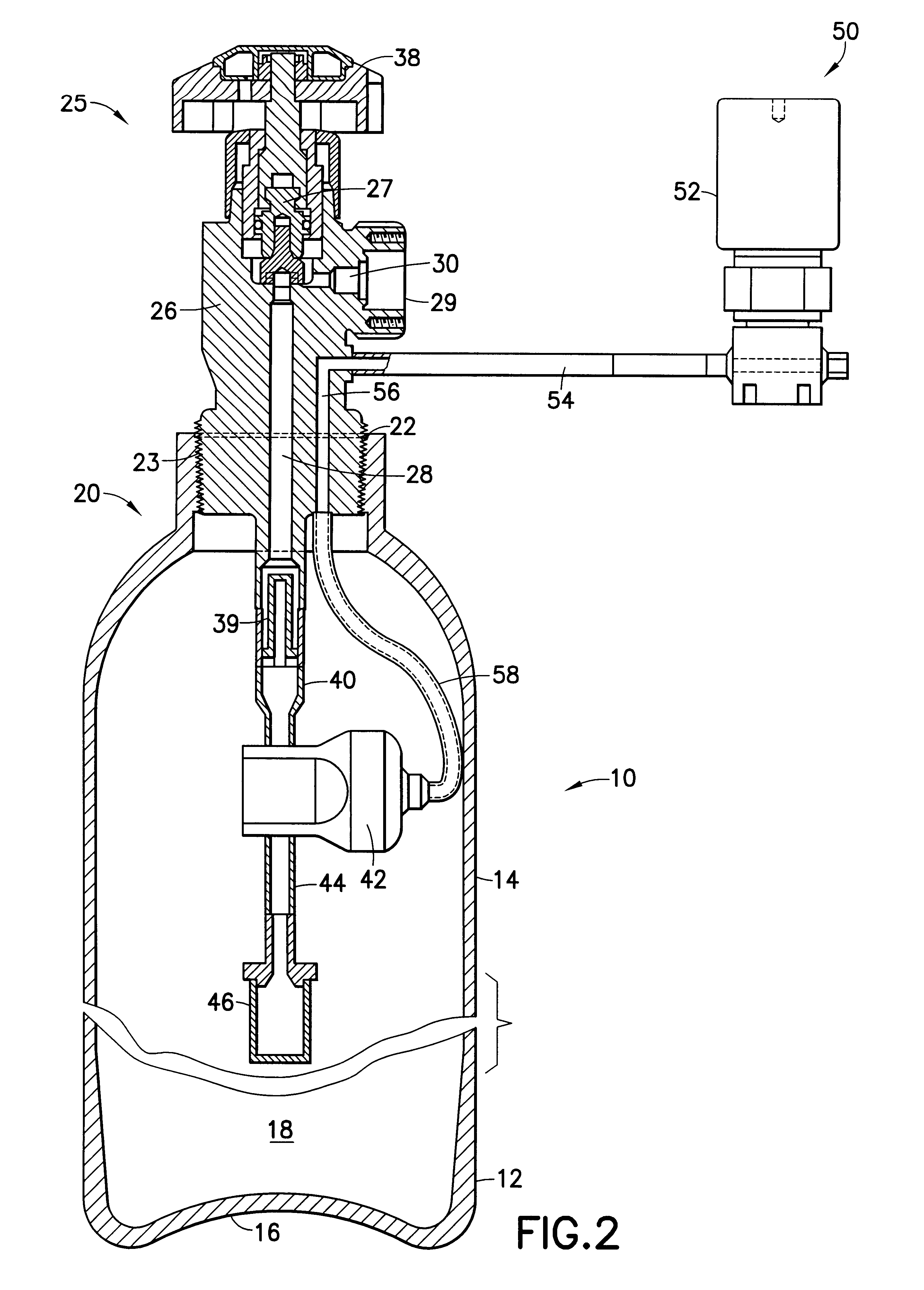
FIG. 3 is a schematic cross-sectional elevation view of a fluid storage and dispensing system according to the present invention, featuring another two ported valve body embodiment. In the FIG. 3 drawing, all corresponding elements and features of the FIG. 1 and FIG. 2 embodiments are correspondingly numbered in FIG. 3 for ease of reference.

The FIG. 3 embodiment differs from the two-ported fluid storage and dispensing system shown in FIG. 2 in that the FIG. 3 embodiment has separate dispensing and fill ports 29 and 34, respectively, and the fill passage 32 is joined at the bottom face of valve body 26 to gas flow line 57. The gas flow line 57 at its opposite end from that joined to the valve body 26 is joined to the regulator 42.

By this arrangement, the fill port in the FIG. 3 embodiment may be coupled to a source of fluid (not shown) for initial charging of the vessel. For such charging operation, the adjustable set point regulator 42 may be set at an appropriate pressure set point...

fourth embodiment

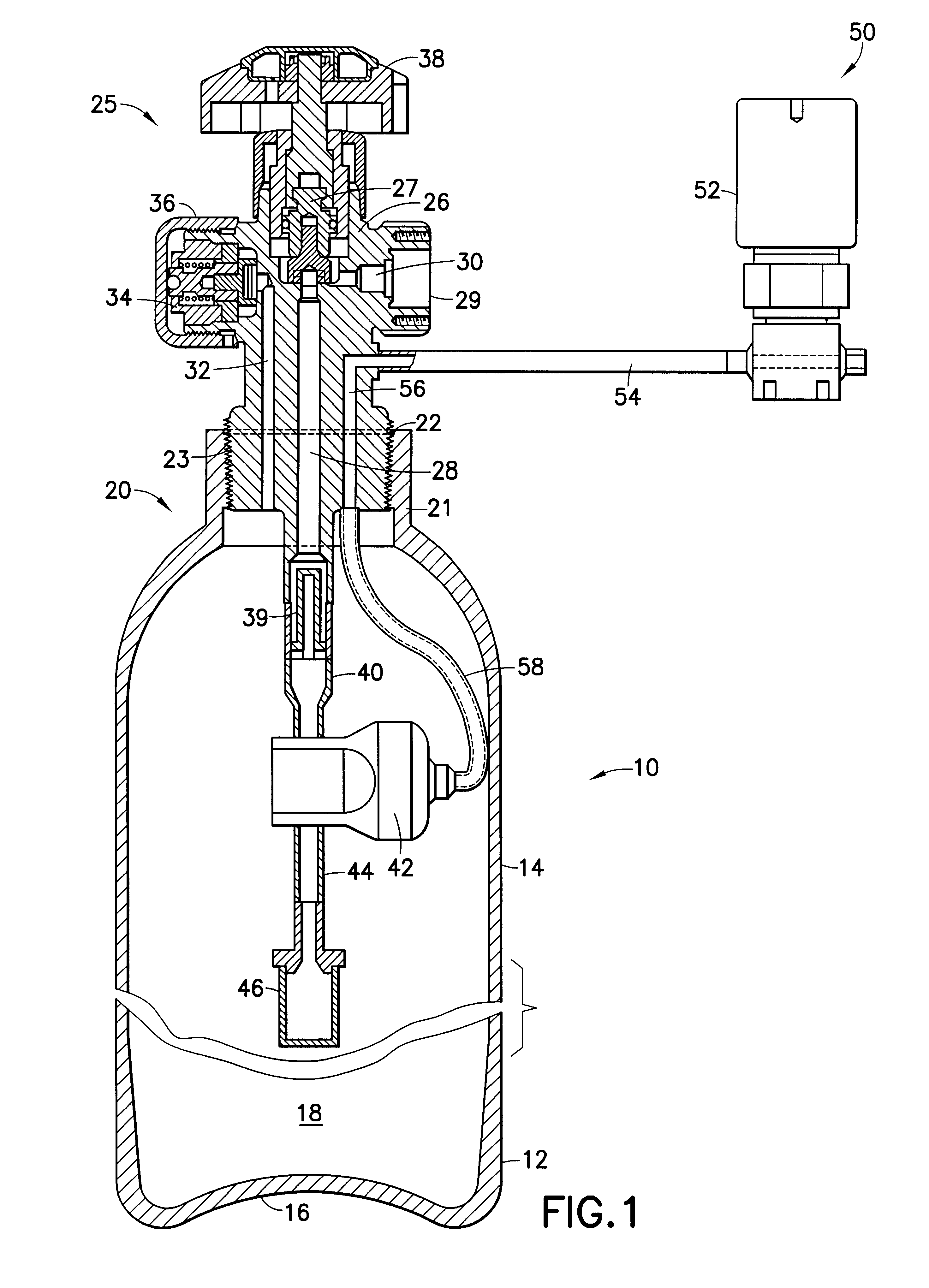
FIG. 4 is a schematic cross-sectional elevation view of a fluid storage and dispensing system according to the present invention. The FIG. 4 embodiment features a three-port valve head body 26 having general similarity in structure to the embodiment of FIG. 1. In FIG. 4, all corresponding elements and features are numbered correspondingly to FIG. 1 for ease of reference.

The FIG. 4 embodiment, in contrast to the fluid storage and dispensing system of FIG. 1, features a second regulator 70 disposed below adjustable set point regulator 42, so that regulator 70 is upstream of regulator 42 in the flow path of the fluid being dispensed from vessel 12 (through particle filter 46, regulator 70, regulator 42, extension tube 40, central vertical passage 28, and gas discharge passage 30 of gas discharge port 29).

The regulator 70, in contrast to the adjustable set point regulator 42, is a set pressure regulator that is fixed or set at a specific pressure set point, which governs its dispensing ...

fifth embodiment

FIG. 5 is a schematic cross-sectional elevation view of a fluid storage and dispensing system according to the present invention. The FIG. 5 embodiment features a three-port valve head body 26 having general similarity in structure to the embodiment of FIG. 1. In FIG. 5, all corresponding elements and features are numbered correspondingly to FIG. 1 for ease of reference.

The FIG. 5 embodiment, in contrast to the fluid storage and dispensing system of FIG. 1, features a second regulator 72 disposed below adjustable set point regulator 42, so that regulator 72 is upstream of regulator 42 in the flow path of the fluid being dispensed from vessel 12 (through particle filter 46, regulator 72, regulator 42, extension tube 40, central vertical passage 28, and gas discharge passage 30 of gas discharge port 29).

The FIG. 5 embodiment has separate dispensing and fill ports 29 and 34, respectively, and the fill passage 32 is joined at the bottom face of valve body 26 to gas flow line 74. The gas...


PUM

PropertyMeasurementUnit
pressureaaaaaaaaaa
pressureaaaaaaaaaa
pressureaaaaaaaaaa

Abstract

A fluid storage and dispensing system including a vessel for holding a fluid, an adjustable set point pressure regulator in the interior volume of the vessel, a dispensing assembly in fluid flow communication with the regulator for dispensing fluid at a pressure determined by the set point of the regulator, and an adjusting assembly exterior to the vessel for in situ adjustment of the set point of the internally disposed regulator. By such arrangement, fluid storage and dispensing operations can have respectively differing regulator set point pressures, as for example a sub-atmospheric pressure set point for storage and a super-atmospheric pressure set point for dispensing.

Description

1. Field of the InventionThis invention relates to a fluid storage and gas dispensing system that may be utilized to store high pressure liquid or other fluid, for dispensing of gas from the system and use of the dispensed gas in an application such as the manufacture of semiconductor devices and materials.2. Description of the Related ArtIn a wide variety of industrial processes and applications, there is a need for a reliable source of process fluid(s).For example, a safe, reliable and efficient fluid supply source is desirable in the field of semiconductor manufacturing, ion implantation, manufacture of flat panel displays, medical intervention and therapy, water treatment, emergency breathing equipment, welding operations, space-based delivery of liquids and gases, etc.U.S. patent application Ser. No. 09 / 067,393 filed Apr. 28, 1998 in the names of Luping Wang and Glenn M. Tom describes a fluid storage and gas dispensing system including a storage and dispensing vessel for holdin...

Claims


Application Information

Patent Timeline
Patent Type & Authority Patents(United States)
IPC IPC(8): F17C13/00F17C13/02F17C13/04F17C7/00F17C9/00
CPCF17C7/00F17C13/025F17C13/04F17C9/00F17C2270/0518F17C2205/0338F17C2205/0391Y02E60/321F17C2201/0109F17C2201/0114F17C2201/032F17C2201/056F17C2203/0636F17C2203/066F17C2203/0663F17C2205/018F17C2205/0326F17C2205/0329F17C2205/0341F17C2205/0385F17C2205/0394F17C2221/014F17C2221/016F17C2221/017F17C2223/033F17C2223/035F17C2223/036F17C2223/038F17C2227/044F17C2250/0626F17C2250/0636F17C2250/072Y02E60/32F17C7/04
Inventor WANG, LUPING
Owner ENTEGRIS INC
Why Eureka
Try Eureka