Self rotating display spherical device

a display device and self-rotating technology, applied in the field of self-rotating and self-powered display devices, can solve the problems of consuming a great deal of electrical power, complex and bulky counter-torque-producing mechanisms, and most prior embodiments that are not totally free of external connection

Inactive Publication Date: 2005-08-30
TURTLETECH DESIGN
View PDF71 Cites 37 Cited by
  • Summary
  • Abstract
  • Description
  • Claims
  • Application Information

AI Technical Summary

Benefits of technology

[0006]The principal and secondary objects of this invention are to provide the simplest and least power-demanding rotating but yet stationary structure that can operate for extremely long periods of time wi...

Problems solved by technology

Most prior embodiments are not totally free of external connection.
If they are not firmly anchored to an outer support, they require complex and...

Method used


Image

  • Self rotating display spherical device
  • Self rotating display spherical device
  • Self rotating display spherical device

Examples


first embodiment

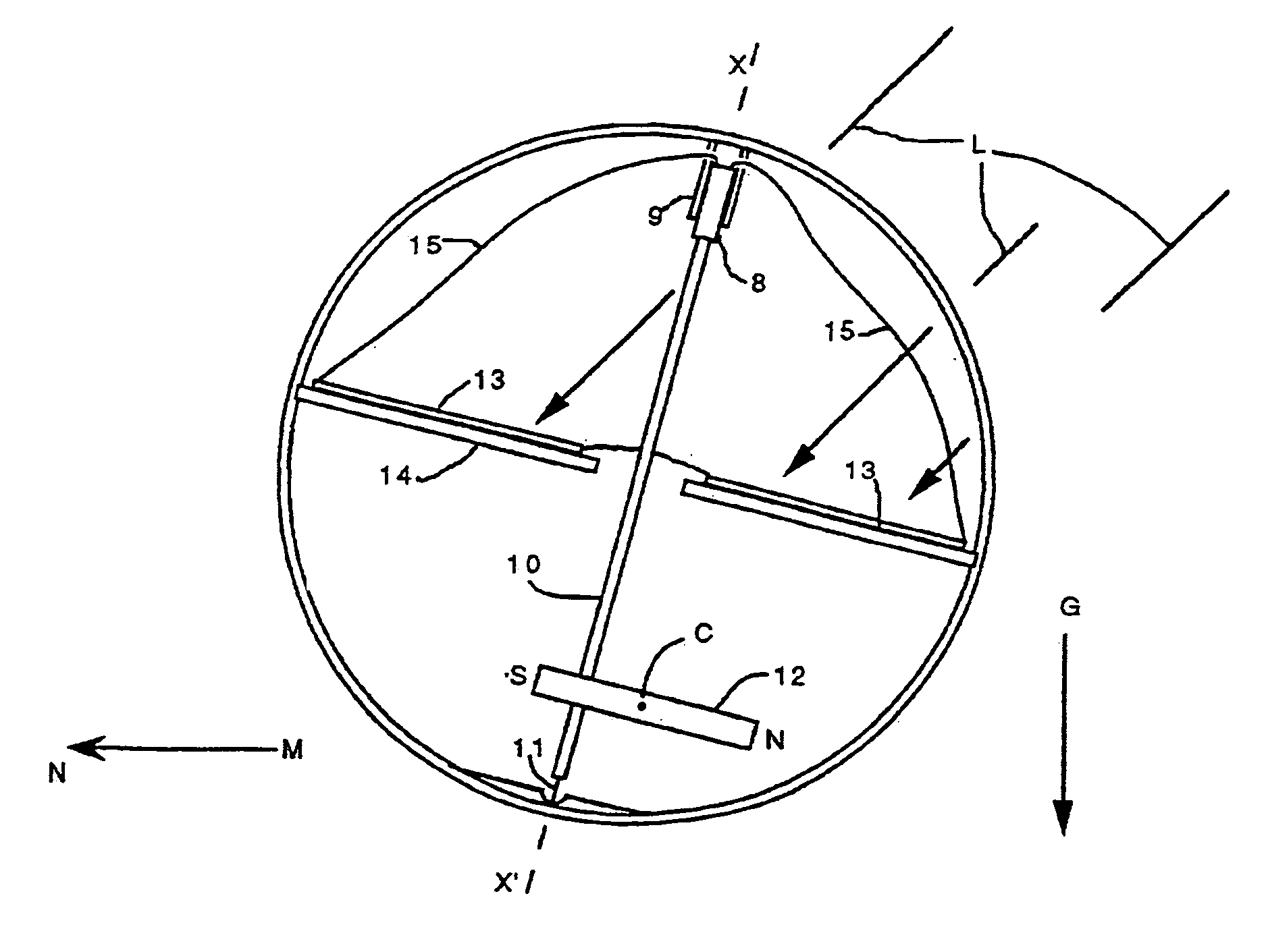
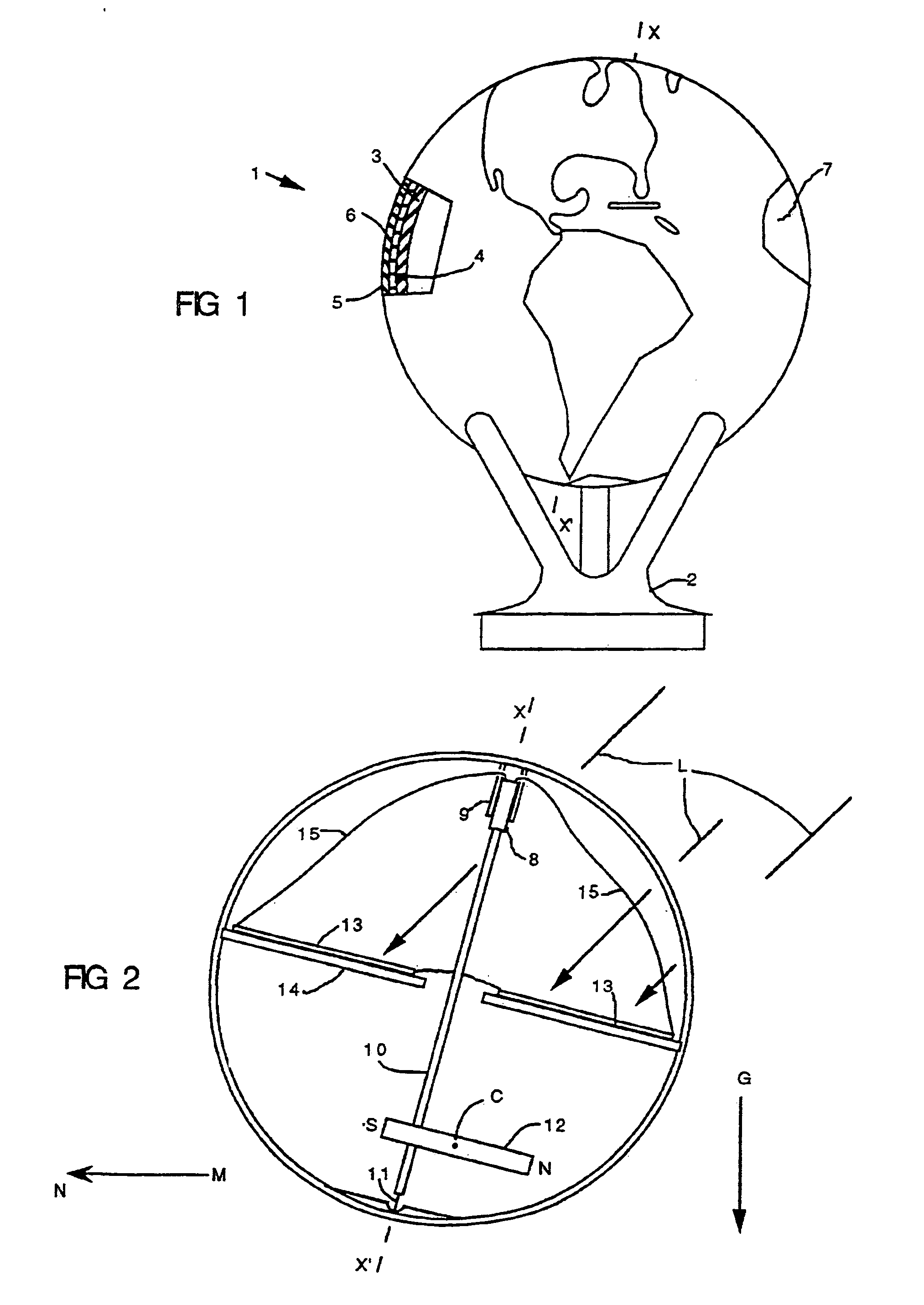
[0027]Referring now to the drawing, there is shown in FIGS. 1 and 2 the invention in the form of a globe 1 which rests on a three-pronged support 2. The globe comprises a spherical, closed and sealed enclosure 3 made of two hemispheric shells of acrylic glued together along an equatorial seam 4. The enclosure 3 is concentrically surrounded by a spherical container 5 preferably made of transparent acrylic in the same manner as the enclosure 3. The enclosure 3 and the container 5 are separated by a small space filled with a liquid 6 so that the enclosure 3 is supported and surrounded by the liquid 6, and can spin upon itself about an axis X–X′ independently of the container 5. Painted or etched upon the outer surface of the enclosure 3 is a graphic design, in this case, a map of the world 7. The weight of the enclosure is appropriately distributed to place the structure in the desired orientation.

[0028]The enclosure 3 is preferably translucent. In other words, it is permeable to light...

embodiment 16

[0032]The first alternate embodiment 16 of the drive mechanism illustrated in FIG. 3, relies on a known relationship between the orientation of an ambient magnetic field and the direction of another ambient field of energy such as another magnetic field, a field of radio waves or, as more specifically taught in this embodiment, a field of light waves impinging upon the enclosure. The enclosure spinning torque is derived from the earth magnetic field M and the directional bearing locator function is achieved by sensing the direction of the light waves L. The electrical motor is constituted by two electromagnets AC and BD positioned on the equatorial septum 14 in a cross-array wherein each electromagnet is oriented radially from the axis of rotation X–X′. Four photosensors a, b, and d are mounted in a pyramidal configuration wherein the photo-sensitive surface of each sensor lies in a different plane than the plane in which the photo-sensitive surface of any one of the other sensors l...

embodiment 30

[0051]In a fourth alternate embodiment 30 of the drive mechanism illustrated in FIGS. 9 and 10, the magnet 21 acts as the directional bearing locator and the photovoltaic collector 13, and is rotatively mounted on a central axle 10. The axle, as well as the equatorial septum 14, are fixedly attached to the enclosure 3. A set of four ring segments a, b, c and d are mounted proximate the top surface of the axle in a cross-array configuration. As the enclosure spins about axis X–X′ which is coincident with the axle 10, a pair of brushes 18 are used to enable the cross-array of electromagnets A, B, C and D in a similar manner as was disclosed in connection with the previously described embodiments. The sequential and alternate distribution of the feeding current to the electromagnets including their polarity commutation are accomplished according the techniques well known to those with ordinary skill in the art.

[0052]It should be understood that the directional bearing locator of the fi...


PUM


Abstract

An intriguing and educational display structure (1) appears to be spinning upon itself without any apparent drive mechanism, power supply or bearing. The structure comprises two concentric hollow spheres (3, 5) spaced apart by a transparent fluid (6). The outer sphere is totally transparent, immobile and may rest on a tripod (2) or other type of support. The inner sphere may be partially transparent or translucent and carries over its surface, a design such as a map of the world (7). The inner sphere rotates within, and independently from the first outer one. The internal, that is self-contained drive mechanism is referenced to either a compass, a light angle detector, or a gravity sensor, and uses either a conventional electrical motor with its own internal field winding and communitator, or one made of a rotor comprising a cross-array of electromagnets (AC, BD) that interact with the earth magnetic field.

Description

PRIOR APPLICATION[0001]This application is a U.S. Domestic Entry of International Patent Application Ser. No. PCT / US00 / 26394 filed Sep. 26, 2000, published Apr. 26, 2001 as International Publication No. WO 01 / 29803 in English which claims the benefit of U.S. Provisional Application Ser. No. 60 / 160,142 filed Oct. 18, 1999.FIELD OF THE INVENTION[0002]The instant invention relates to self-starting and self-powered display devices, and more particularly, to self-spinning globes powered by radiated energy.BACKGROUND OF THE INVENTION[0003]Various types of novelty structures which move with either no apparent support, drive mechanism, or power input are often used as toys, decorative conversation pieces or advertising media. Various embodiments of such structures have been disclosed in U.S. Pat. No. 5,435,086 Huang et al., Japanese Patents Nos. 10137451, 101431101, and 10171383, all by Hirose Mamoru, Japanese Patents Nos. 7210081, 7219426, and 7239652 all to Taragi Hiroshi and German Paten...

Claims


Application Information

Patent Timeline
IPC IPC(8): G09B27/08G09F19/02G09F19/00G09B27/00F16C39/06
CPCF16C39/063G09B27/08G09F19/02G09F19/12
Inventor FRENCH, WILLIAM W.
Owner TURTLETECH DESIGN
Why Eureka
Try Eureka