Modular power distribution unit, module for the power distribution unit, and method of using the same

a power distribution unit and module technology, applied in the direction of electrical apparatus casings/cabinets/drawers, manufacturing tools, coupling device connections, etc., can solve the problems of increasing the cost of users, limiting the selection of pdus, and not including a sufficient variety of pdus

Inactive Publication Date: 2005-08-30
DONAHUE IV WILLIAM F
View PDF27 Cites 172 Cited by
  • Summary
  • Abstract
  • Description
  • Claims
  • Application Information

AI Technical Summary

Benefits of technology

[0006]The power distribution unit of the present disclosure allows the electric power to be effectively changed or upgraded to accommodate the new power requirements without interrupting power to existing attached systems or without incurring significant increased cost or inconvenience for users.
[0009]In another aspect of the present disclosure, the power modules have the capability to be “hot-swapped,” where existing modules may be removed and replaced without shutting down any other modules or without the shutting down the electric power to the power distribution unit itself.

Problems solved by technology

Commercially available PDUs typically have fixed plug receptacles and breakers, the selection of which is very limited.
Frequently, the available PDUs may not include a sufficient variety of receptacles for the different equipment that are used in such environments.
Thus, the limited configurations of plug receptacles in presently available PDUs increases the expense to the user and increases the amount of space used.
This can create many redundant or unuseable plug receptacles that will go unused, and that the user otherwise would not order.
There are many disadvantages to requiring an electrician to hard-wire each additional individual PDU.
The PDU cannot be installed immediately, because the services of an electrician must be scheduled.
In addition, when equipment is shut off, or is not powered redundantly, workers and systems are no longer productive.
Various electrical receptacles of certain configurations and power ratings must be supplied or the new equipment cannot operate.

Method used


Image

  • Modular power distribution unit, module for the power distribution unit, and method of using the same
  • Modular power distribution unit, module for the power distribution unit, and method of using the same
  • Modular power distribution unit, module for the power distribution unit, and method of using the same

Examples


Embodiment Construction

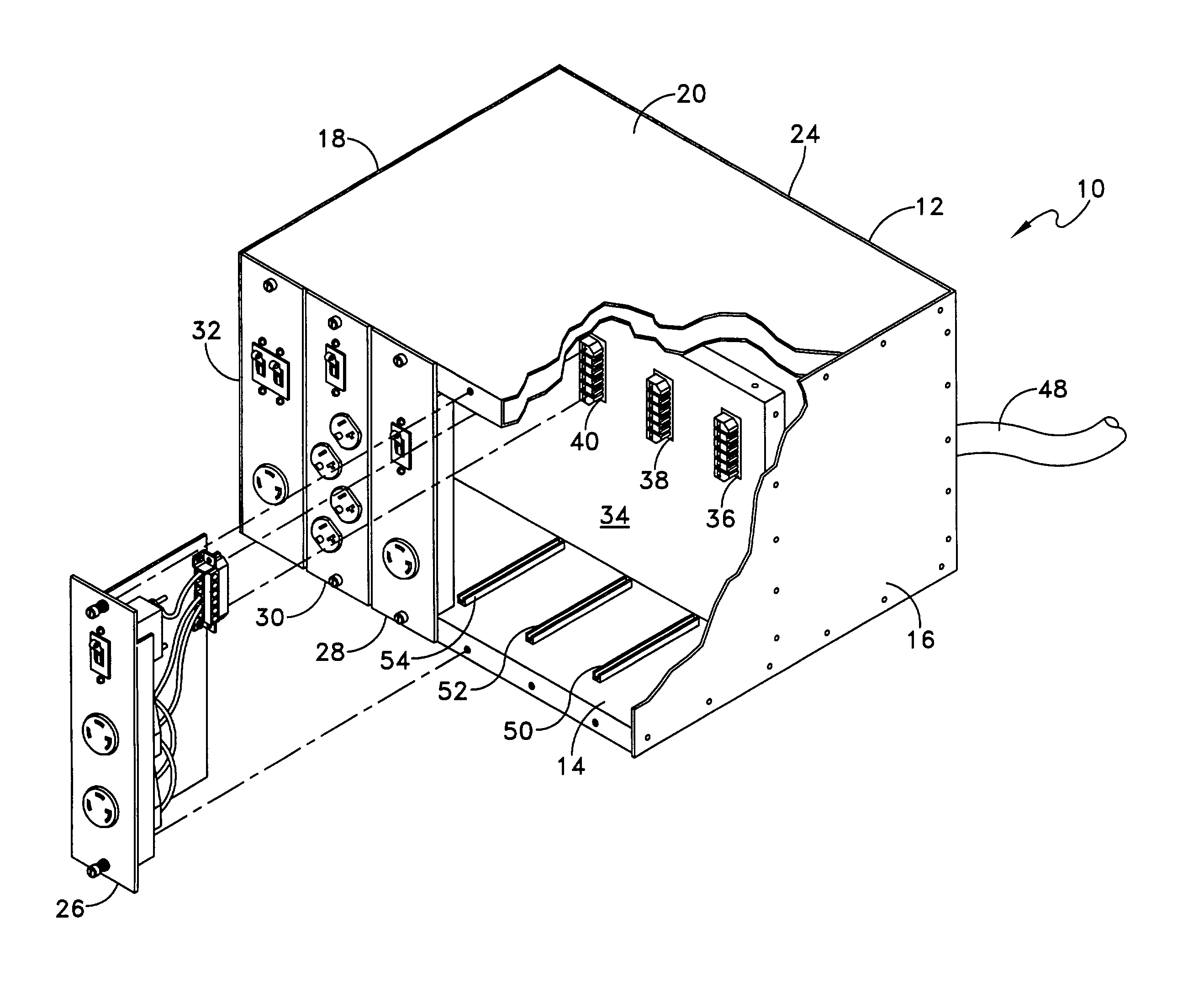
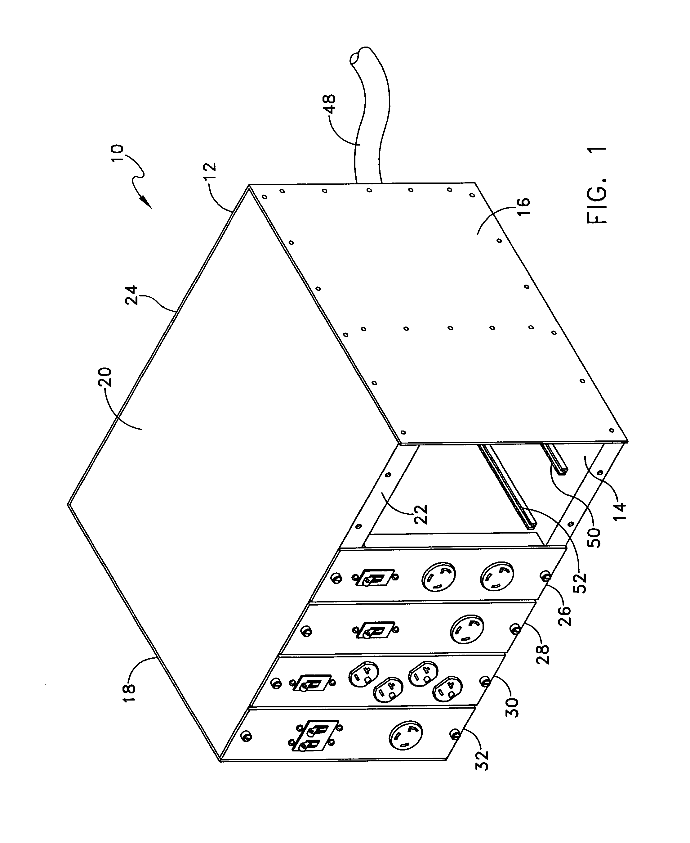
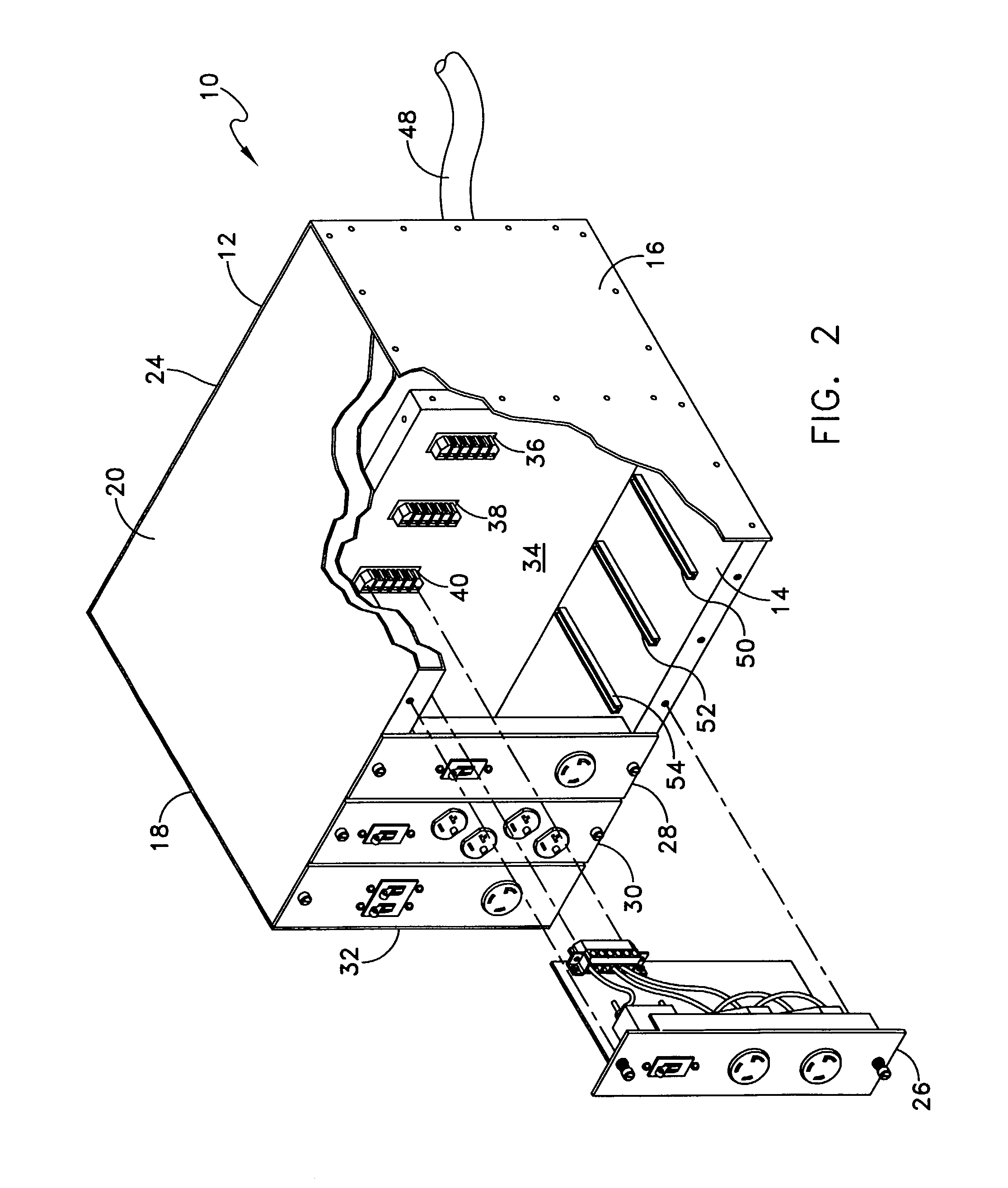
[0023]The power distribution unit 10 of the present disclosure allows users to select configurations of plugs and receptacles to be compatible with the user's specific needs. The system has a frame and module construction that is scalable and customizable, as will be described.

[0024]A preferred embodiment of the a power distribution unit 10 according to the present disclosure is illustrated initially with reference to FIGS. 1 and 2, taken together, which show a front perspective view of the present disclosure. The power distribution unit 10 incorporates a frame 12 in the form of a box-shaped housing. The frame 12 includes a first support member 14, side panels 16 and 18, top panel 20, front panel 22 and rear panel 24. The frame 12 and its components are preferably fabricated from sheet steel to provide rigidity and durability, although other materials, may be contemplated. In use, the frame 12 may be mounted in an equipment rack or be floor mounted, depending on the size of the fram...


PUM


Abstract

A modular power distribution unit (PDU) for supplying electric power to attached equipment in environments such as data centers, computer rooms, and communication centers, where power requirements for attached equipment may vary. The power distribution unit includes a frame and one or more user-replaceable power modules, which fit into slots in the frame. Each power module provides one of more plug receptacles for attaching equipment to provide power thereto. The power modules are available in a variety of receptacle types, receptacle numbers, and power rating configurations to accommodate various equipment in a particular environment, as needed. The frame includes an internal connector panel for distributing power from a power source to the power modules when they are inserted in the frame. The power modules may be removed, installed, and interchanged in the frame without interrupting power to other power modules or to the power distribution unit.

Description

RELATED CASES[0001]Priority is hereby claimed under 35 U.S.C. § 119(e) to commonly owned and U.S. Provisional Patent Application No. 60 / 333,794 which was filed on Nov. 28, 2001.TECHNICAL FIELD[0002]The present application is directed to a modular power distribution unit and method of use and, in particular, to a hot-swappable modular distribution unit and method of use.RELATED ART[0003]Many types of power distribution units (PDUs) are available for distributing power to components in environments such as, for example, data centers, computer rooms, and communication centers. Presently available PDU systems typically include a box with fixed devices. Commercially available PDUs typically have fixed plug receptacles and breakers, the selection of which is very limited. Frequently, the available PDUs may not include a sufficient variety of receptacles for the different equipment that are used in such environments. When that is the case, users must order additional PDUs to accommodate th...

Claims


Application Information

Patent Timeline
Patent Type & Authority Patents(United States)
IPC IPC(8): H02B1/26H02B1/00B25B23/04H01R13/514H01R13/66H01R13/703H01R27/02
CPCH01R13/514H01R13/7038H01R27/02H01R13/6658
Inventor DONAHUE, IV, WILLIAM F.
Owner DONAHUE IV WILLIAM F
Why Eureka
Try Eureka