Machine vision system and method for estimating and tracking facial pose

a machine vision and facial pose technology, applied in image analysis, instruments, computing, etc., can solve problems such as failure to fully exploit the capabilities of the computer, inability to run only facial expression tracking techniques at realistic camera frame rate, and confusion in techniques

Inactive Publication Date: 2005-08-30
MICROSOFT TECH LICENSING LLC
View PDF4 Cites 67 Cited by
  • Summary
  • Abstract
  • Description
  • Claims
  • Application Information

AI Technical Summary

Problems solved by technology

Although this one-sided interaction is common it fails to fully exploit the capabilities of the computer.
Determining a user's facial pose in real time, however, presents many challenges.
One problem with current real-time head tracking techniques, however, is that these techniques often are confused by waving hands or changing illumination.
In addition, techniques that track only faces do not run at realistic camera frame rates or do not succeed in real-world environments.
Moreover, head tracking techniques that use visual processing modalities may work well in certain situations but fail in others, depending on the nature of the scene being processed.
Current visual modalities, used singularly, are not discriminating enough to detect and track a head robustly.

Method used


Image

  • Machine vision system and method for estimating and tracking facial pose
  • Machine vision system and method for estimating and tracking facial pose
  • Machine vision system and method for estimating and tracking facial pose

Examples


working example

[0074]IV. Operational Details and Working Example

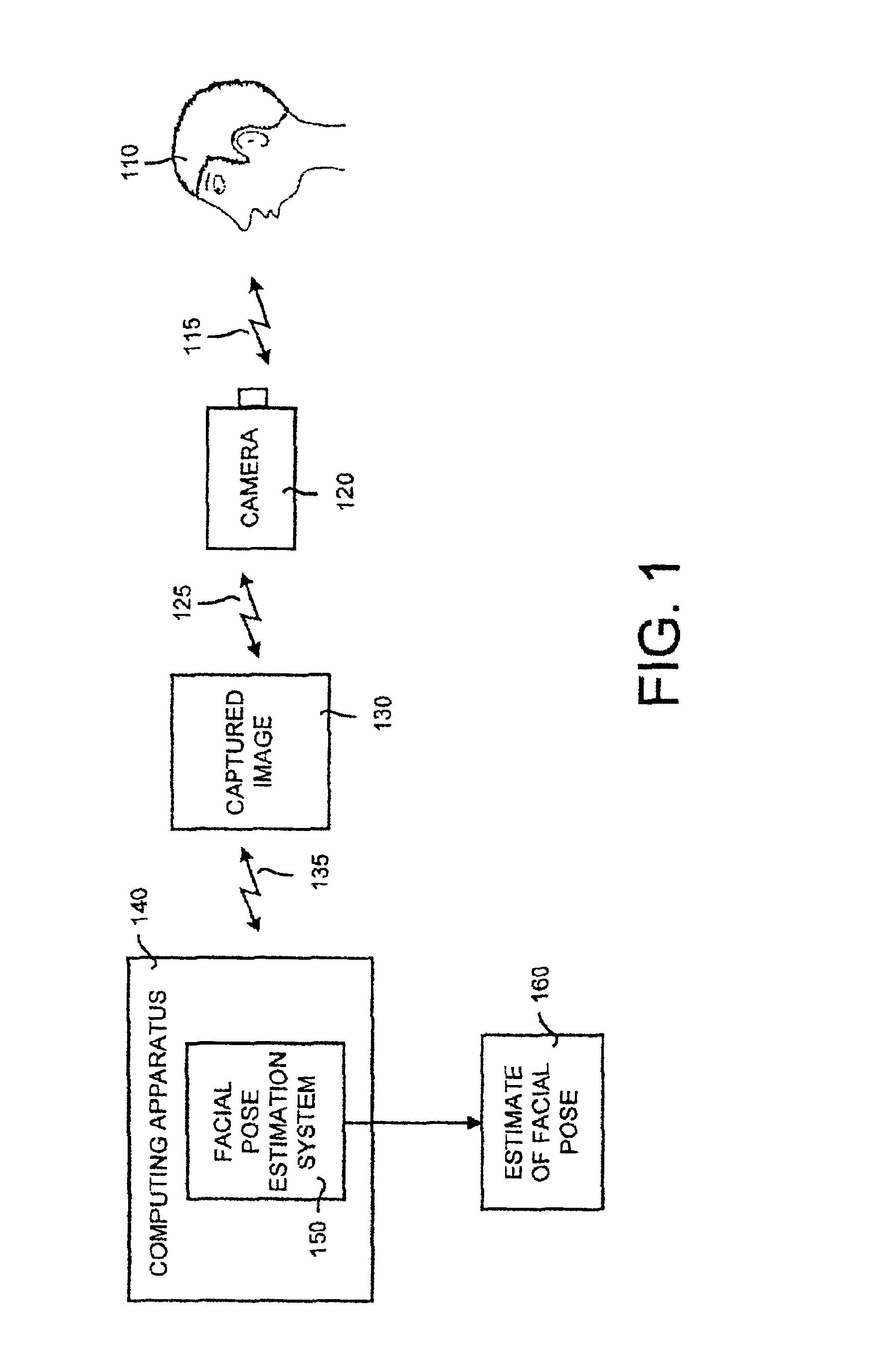
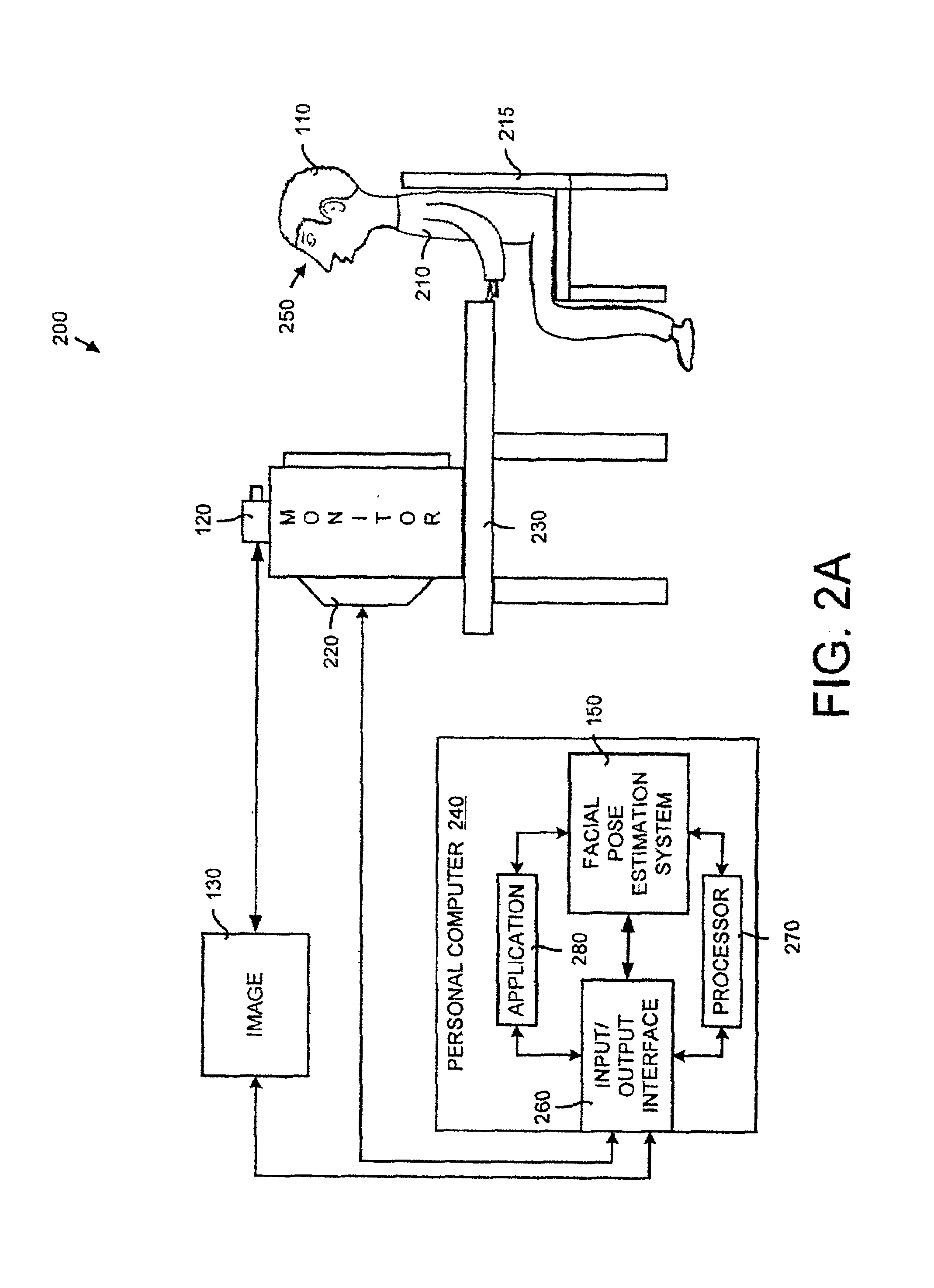
[0075]The following working example is used to illustrate the operational details of the invention. This working example includes the implementation of FIGS. 2A and 2B in which the facial pose estimation system 150 is incorporated into the attention detection system 200. This working example is provided as an example of one way in which facial pose estimation system may operate and be used. It should be noted that this working example is only one way in which the invention may operate and be used, and is provided for illustrative purposes only.

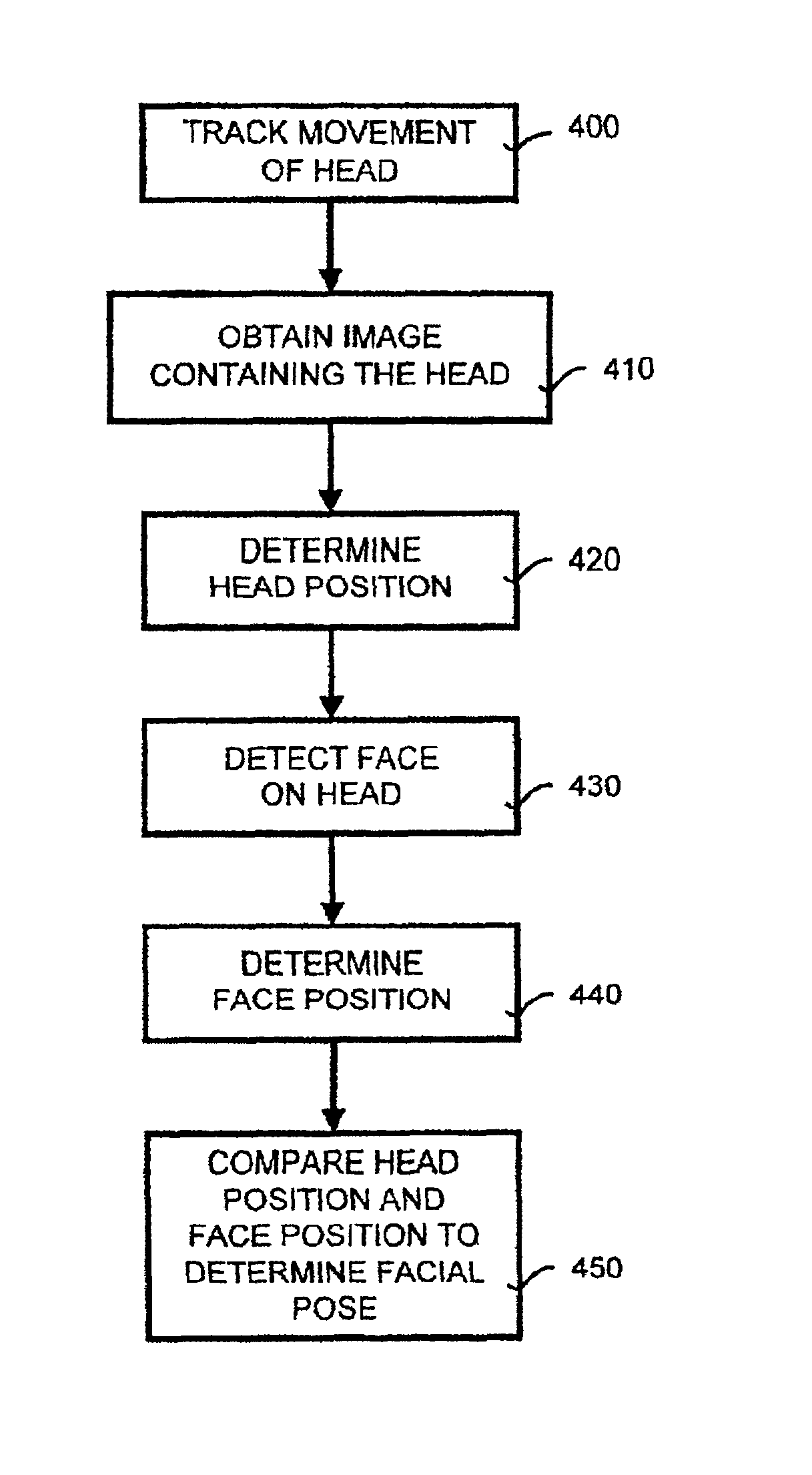
[0076]The comparison of the head and face positions may be achieved by using one of at least two techniques. The working example presented uses a first technique outlined above that involves determining a center of the user's head and constructing a head line between the head center and the center of the camera. Next, a face on the head is detected and the center of the face is computed. A face ...


PUM


Abstract

The present invention includes in a system and method for estimating and tracking an orientation of a user's face by combining head tracking and face detection techniques. The orientation of the face, or facial pose, can be expressed in terms of pitch, roll and yaw of the user's head. Facial pose information can be used, for example, to ascertain in which direction the user is looking. In general, the facial pose estimation method obtains a position of the head and a position of the face and compares the two to obtain the facial pose. In particular, a camera is used to obtain an image containing a user's head. Any movement of the user's head is tracked and the head position is determined. A face then is detected on the head and the face position is determined. The head and face positions then are compared.

Description

BACKGROUND OF INVENTION[0001]1. Technical Field[0002]The present invention relates in general to object tracking and detection and using machine vision and more particularly to a system and a method for estimating and tracking an orientation of a user's face using a combination of head tracking and face detection techniques.[0003]2. Related Art[0004]Traditional interaction between a user and a computer occurs with the computer waiting passively for the user to dictate its actions. Through input devices, such as a keyboard and a mouse, the user communicates actions and intentions to the computer. Although this one-sided interaction is common it fails to fully exploit the capabilities of the computer.[0005]It is desirable to have the computer play a more active role in interacting with the user rather than merely acting as a passive information source. A more interactive design involves linking the computer to a video camera so that the computer can interact with the user. The compute...

Claims


Application Information

Patent Timeline
Patent Type & Authority Patents(United States)
IPC IPC(8): G06T7/20G06T7/00G06V10/24
CPCG06K9/00228G06K9/32G06T7/0044G06T7/208G06K2009/3291G06T7/74G06T7/277G06V40/161G06V10/62G06V10/24
Inventor TOYAMA, KENTARO
Owner MICROSOFT TECH LICENSING LLC
Why Eureka
Try Eureka