Mortise lock status indicator

a status indicator and mortise lock technology, applied in the field of mortise locks, can solve the problems of inability to meet the requirements of security, easy tampering or vandalism of indicator products currently on the market,

Inactive Publication Date: 2005-09-06
SARGENT MANUFACTURING CO INC
View PDF35 Cites 50 Cited by
  • Summary
  • Abstract
  • Description
  • Claims
  • Application Information

AI Technical Summary

Problems solved by technology

Such indicator products currently on the market, however, do not have the required security and can be easily tampered with or vandalized.

Method used


Image

  • Mortise lock status indicator
  • Mortise lock status indicator
  • Mortise lock status indicator

Examples


Embodiment Construction

)

[0027]In describing the preferred embodiment of the present invention, reference will be made herein to FIGS. 1-6B of the drawings in which like numerals refer to like features of the invention.

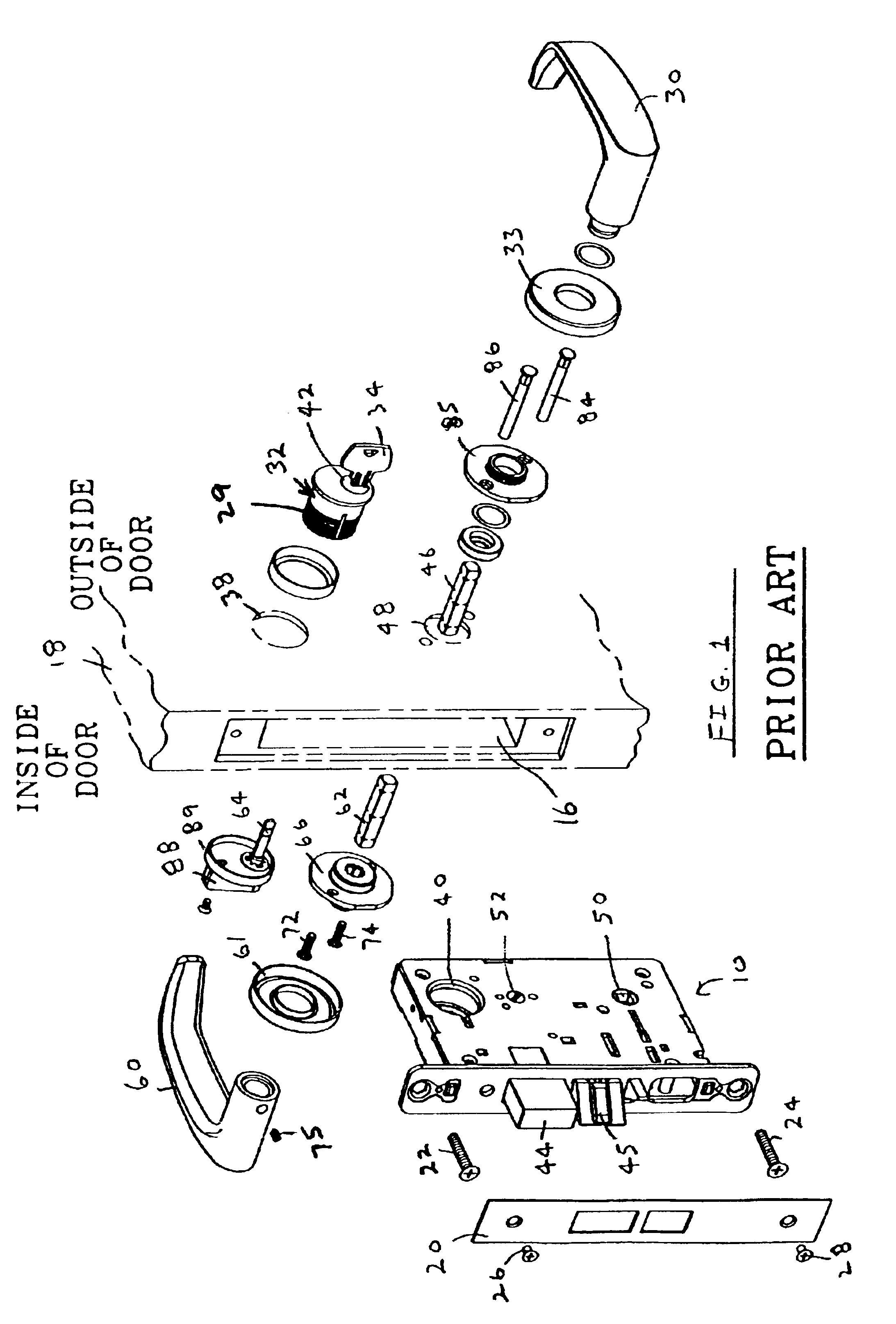
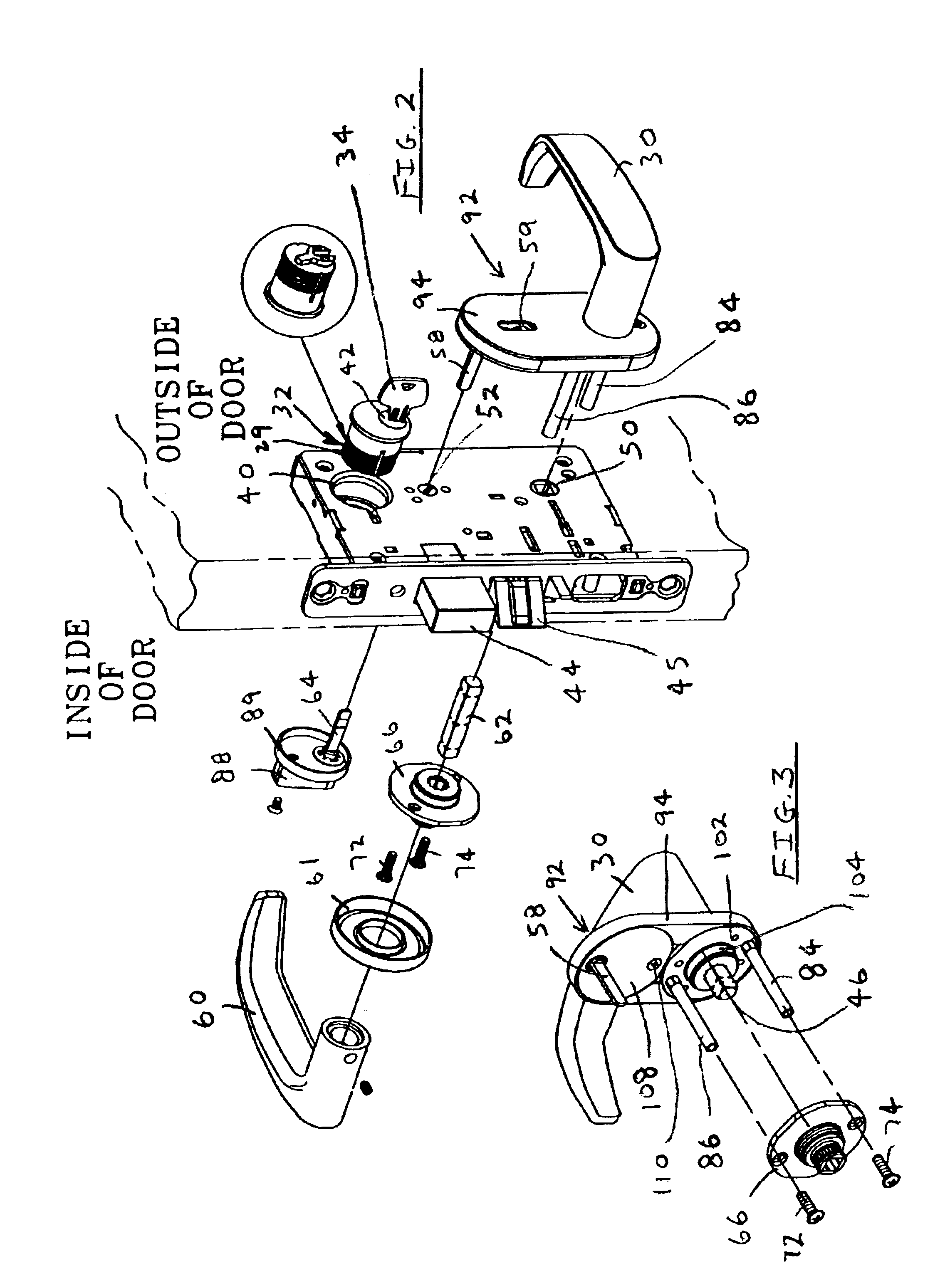
[0028]Referring to FIG. 1, a conventional mortise-type lockset of the prior art includes a mortise lock 10, an outer lever handle 30, and an inner lever handle 60. The mortise lock 10 fits within a mortise opening 16 in door 18 and is covered by decorative plate 20.

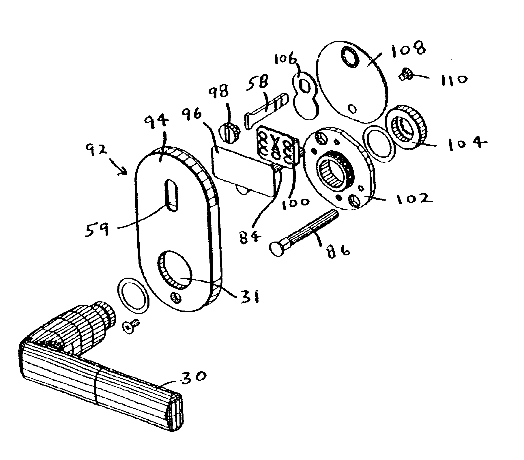
[0029]The mortise lock 10 is held in door 18 with screws 22, 24 and these screws are covered by the decorative plate 20 which is held onto the edge of the mortise lock 10 with screws 26, 28. The mortise lock 10, as well as the inner lever handle 60 and outer lever handle 30, are substantially unchanged from the prior art, and no modifications are needed to these elements in order to provide the mortise lock visual indicator of the invention. It is highly preferred, however, that the visual indicator and outer lever handle be combi...


PUM


Abstract

A conventional mortise lock is provided with a visual status indicator to show whether the room is occupied or vacant. The mortise lock output, which operates the deadbolt, is used to linearly move an indicator slide positioned on the outside of the door by a rotating indicator spindle which is in communication with the mortise lock output and indicator slide. The visual status indicator has an opening which is covered by a transparent high strength, impact resistant material such as LEXAN plastic. A preferred embodiment combines the outer lever door handle controller and visual status indicator in a single housing.

Description

BACKGROUND OF THE INVENTION[0001]1. Field of the Invention[0002]The present invention relates to mortise locks and, in particular, to a high security and tamper proof visual indicator mounted on the outside of the door and in communication with the lock to indicate whether the door is locked or unlocked.[0003]2. Description of Related Art[0004]Mortise locksets generally include the mortise lock and inner and outer handle controllers or trim sets which operate the mortise lock. The mortise lock is mortised into the door and usually includes the latching mechanism which secures the door to the doorframe when the door is closed, as well as the locking mechanism which prevents the latching mechanism from being retracted when the door is locked.[0005]The handle controllers are generally surface mounted on opposite sides of the door and have handles which operate the latching mechanism. In most current designs, the handle on each handle controller is directly connected to a shaft that ext...

Claims


Application Information

Patent Timeline
Patent Type & Authority Patents(United States)
IPC IPC(8): E05B41/00
CPCE05B41/00Y10S70/59Y10T70/5226Y10T70/8027
Inventor HUANG, RICHARD HAI
Owner SARGENT MANUFACTURING CO INC
Why Eureka
Try Eureka