Pneumatic percussive tool with a movement frequency controlled idling position

a technology of pneumatic percussive tools and idling positions, which is applied in the direction of portable percussive tools, boring/drilling equipment, drilling machines and methods, etc., can solve the problems of heavy hammer that is subject to wear, requires constructive space, and requires a large amount of spa

Inactive Publication Date: 2005-09-06
WACKER NEUSON SE
View PDF14 Cites 25 Cited by
  • Summary
  • Abstract
  • Description
  • Claims
  • Application Information

AI Technical Summary

Benefits of technology

[0007]The underlying object of the invention is to provide a pneumatic spring hammer mechanism in which the advantages of the transm

Problems solved by technology

Such a centrifugal force coupling is technically costly, requires constructive space,

Method used


Image

  • Pneumatic percussive tool with a movement frequency controlled idling position
  • Pneumatic percussive tool with a movement frequency controlled idling position
  • Pneumatic percussive tool with a movement frequency controlled idling position

Examples


Embodiment Construction

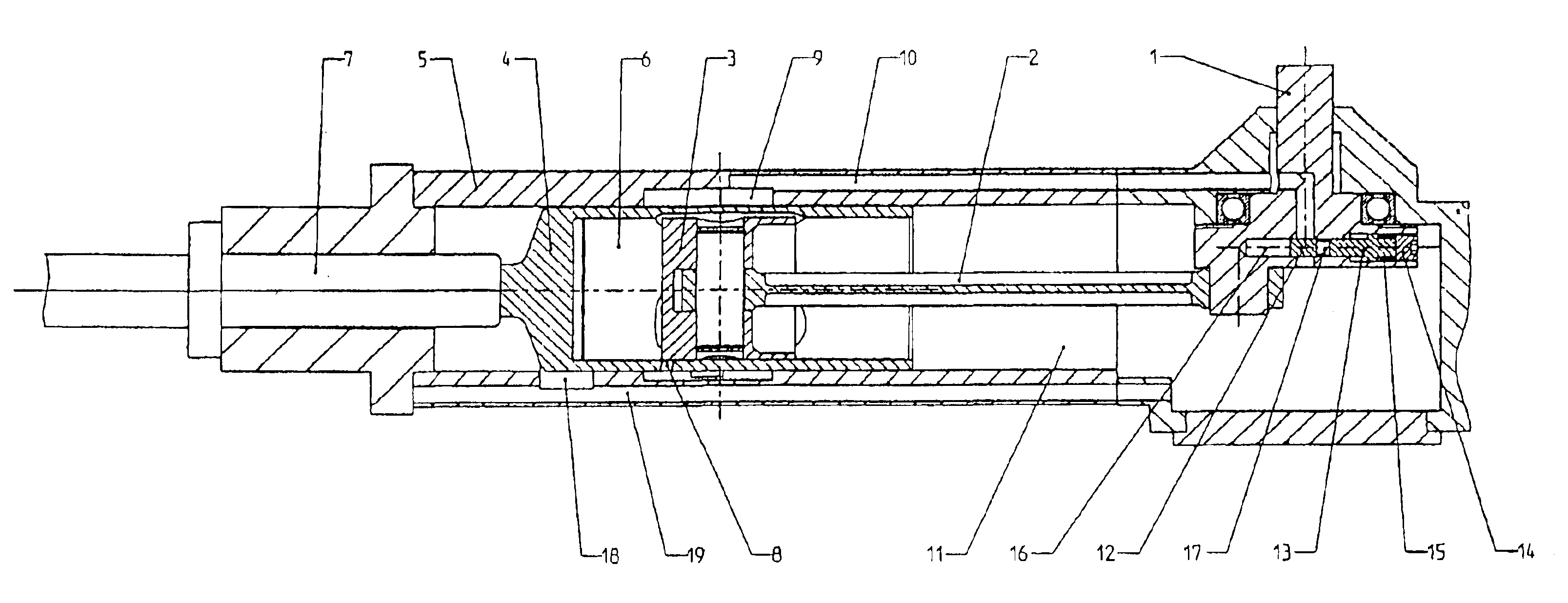
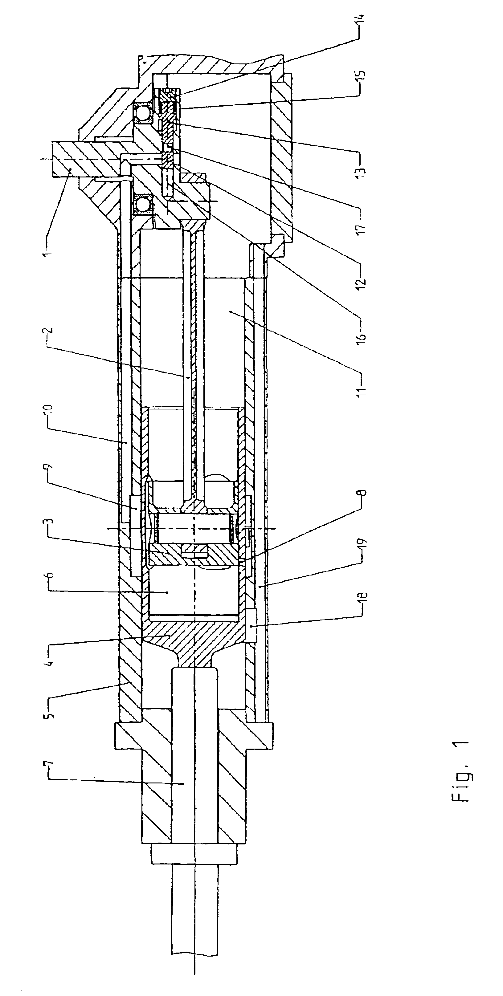
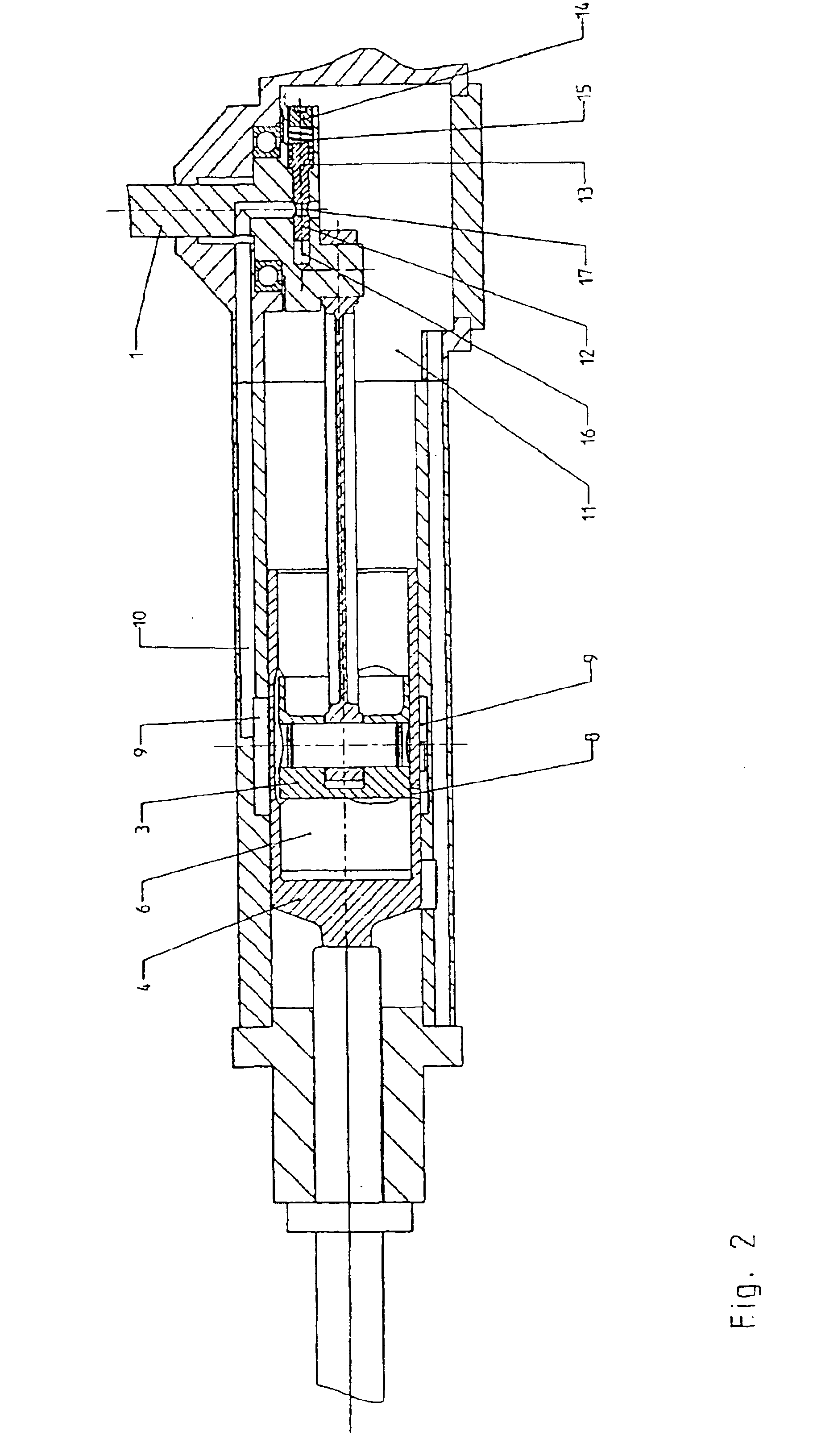
[0024]FIG. 1 shows a section through a pneumatic spring hammer mechanism according to the present invention, in percussive operation.

[0025]Via a connecting rod 2, a crankshaft 1 drives a drive piston 3 back and forth axially. Drive piston 3 is housed in a percussion piston 4, which in turn can be moved back and forth axially inside a tube-shaped hammer mechanism housing 5.

[0026]Such a pneumatic spring hammer mechanism is also designated a hollow-hammer hammer mechanism, and is known.

[0027]In percussive operation, drive piston 3 moves back and forth inside percussion piston 4, which causes an air spring to build up in a hollow space 6 formed between drive piston 3 and percussion piston 4. When drive piston 3 moves forward (to the left in FIG. 1), the air in hollow space 6 is compressed. The energy of the air compressed as an air spring is emitted to percussion piston 4 and likewise drives it forward, against a shaft 7 (shown schematically) of a chiseling tool. Instead of shaft 7, a r...


PUM

PropertyMeasurementUnit
Speedaaaaaaaaaa
Areaaaaaaaaaaa
Weightaaaaaaaaaa

Abstract

The invention relates to a pneumatic percussive tool for a paving breaker and/or a hammer drill comprising a drive piston which is displaceable both backwards and forwards by a crankshaft and arranged in a percussion piston which is displaceable both backwards and forwards. A hollow chamber is connected to a compensating chamber by an idling air channel and embodied between the drive piston and the percussion piston in order to receive a pneumatic spring. A valve is arranged in the idling air channel, the opening and closing position thereof depending on the rotational speed of the crankshaft. If the rotational speed of the crankshaft falls below a predetermined value, the valve opens the connection between the hollow chamber and the compensating chamber so that a pneumatic spring can no longer be to embodied in the hollow chamber and the pneumatic percussion tool is placed in a idling position.

Description

BACKGROUND OF THE INVENTION[0001]1. Field of the Invention[0002]The present invention relates to a pneumatic spring hammer mechanism or pneumatic percussive tool for a percussive hammer or drill hammer, according to the preamble of patent claim 1.[0003]2. Description of the Related Art[0004]Pneumatic spring hammer mechanisms have long been known in various specific embodiments in which a drive piston is moved back and forth by a crankshaft. In front of the drive piston there is situated a percussion piston that can likewise be moved back and forth, so that between the drive piston and the percussion piston there is formed a hollow space that accommodates an air spring. This air spring, which acts as an air cushion, transmits the movement of the driven drive piston to the percussion piston, which thus follows the movement of the drive piston with a chronological delay. Finally, the percussion piston impacts a shaft of a tool, or of an intermediately connected die, and transfers its i...

Claims


Application Information

Patent Timeline
IPC IPC(8): B25D11/00B23B45/16B25D11/12B25D9/18
CPCB25D11/005B25D2250/221
Inventor BERGER, RUDOLFLYSEK, MIRKOSCHMID, WOLFGANG
Owner WACKER NEUSON SE
Why Eureka
Try Eureka