Magnetic alignment marking of hard disks

a technology of magnetic alignment and hard disk, applied in the field of magnetic alignment marking of hard disk, can solve the problems of exceeding the tolerance of the eccentricity of the drive's servo system, the need to mount the disk, and the inability to switch between them without performing a seek or some other alignment techniqu

Inactive Publication Date: 2005-09-06
SEAGATE TECH LLC
View PDF18 Cites 13 Cited by
  • Summary
  • Abstract
  • Description
  • Claims
  • Application Information

AI Technical Summary

Benefits of technology

[0020]The marks may be written and sensed by means other than the servo-writer's head or the disk drive's head. In one form, the pattern is both written and sensed by a “fixed” electromagnet. In another fo...

Problems solved by technology

However, this approach also introduces a number of problems due to the fact that the disks themselves are not assembled onto the disk drive spindle at the time servo tracks are written.
One of the problems is that the disk must be mounted onto the drive spindle in the same “orientation” it was written.
A second problem occurs when two (or more) such prerecorded MDW disks are mounted in a single disk drive.
If the respective tracks were significantly misaligned in some fashion, switching between them without performing a seek or some other alignment technique would not be possible.
A third problem caused by writing servo data while the disk is mounted on a different spindle is track eccentricity.
If the disk is mounted on the disk drive's spindle in a manner that is significantly off center from the way it was written on the servo writer, it will exceed the drive's servo system eccentricity tolerance....

Method used


Image

  • Magnetic alignment marking of hard disks
  • Magnetic alignment marking of hard disks
  • Magnetic alignment marking of hard disks

Examples


Embodiment Construction

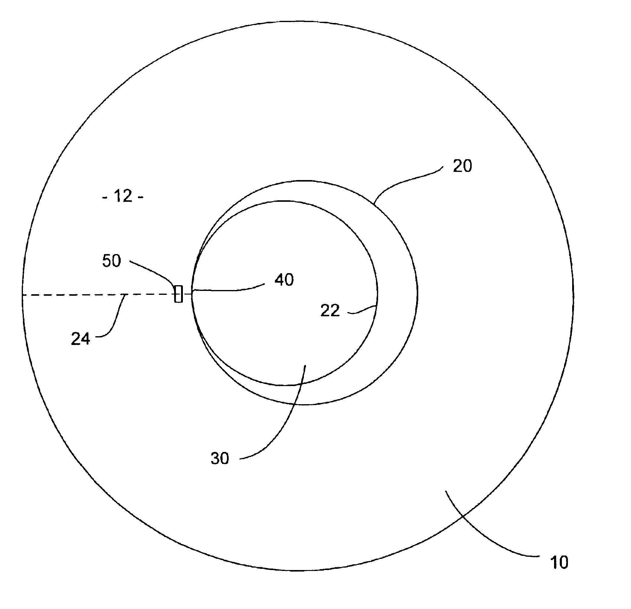
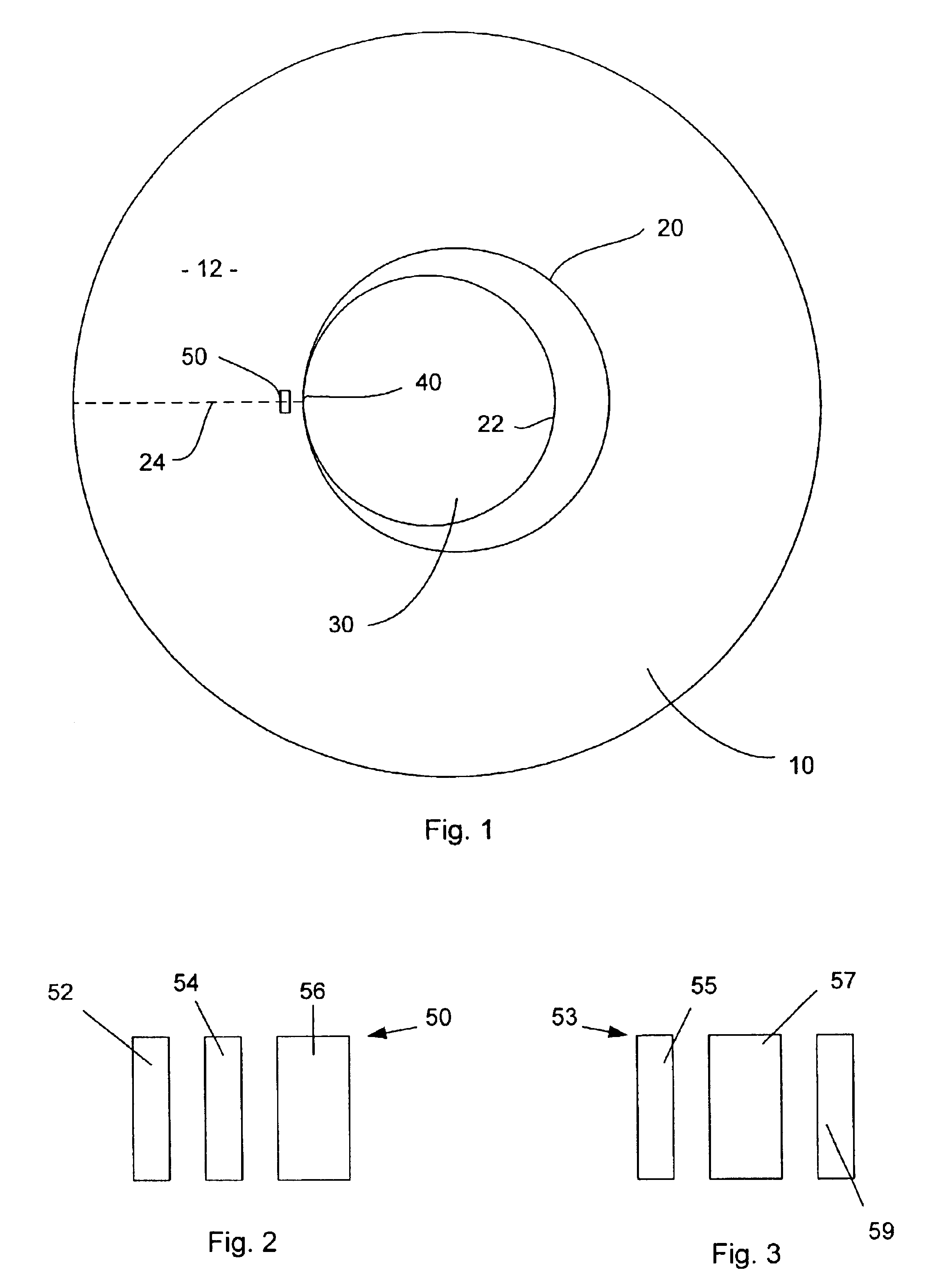
[0029]FIG. 1 illustrates, by exaggeration, a magnetic hard disk 10 biased such that it's inner diameter 20 abuts against the hub 22 of spindle 30 at location 40. FIG. 1 further illustrates a magnetic alignment mark 50 located on top surface 12 of the hard disk 10. This magnetic mark is located in a defined relationship to the abutment location 40. As illustrated in the figure, a preferred location for the magnetic alignment mark 50 is near the inner diameter 20 and aligned on a radial 24 that passes through both the alignment mark 50 and abutment location 40. In this manner, the detection of the alignment mark 50 determines the location 40. Appropriate robotic tooling, not shown, may then bias the disk such that the disk inner diameter 20 abuts the spindle hub 22 at location 40.

[0030]The same bias and location technique may be used for bias-locating the disk 10 on either a servo track writer's spindle or a disk drive's spindle. For this reason, spindle 30 in the figure refers generi...


PUM


Abstract

Magnetic alignment marks are recorded on a recording surface of a magnetic hard disk to mark the location where the disk is abutted against the hub of the spindle of a multiple-disk servo-writer. The alignment marks for each recording surface may be different so as to distinguish between top and bottom disk surfaces so that when the discs are assembled onto the spindle of a disk drive they may be assembled with the proper orientation, i.e., the top surface is mounted “up.” The marks may be large, low frequency patterns that are both written and detected by non contact means other than the servo-track writer's or the disk drive's heads.

Description

CROSS-REFERENCE TO RELATED APPLICATIONS[0001]This application claims benefit of U.S. provisional patent application Ser. No. 60 / 371,953, filed on Apr. 10, 2002, which is hereby incorporated by reference.BACKGROUND OF THE INVENTION[0002]1. Field of the Invention[0003]The invention relates to field of disk drives and more particularly to methods for writing servo tracks on magnetic hard disks.[0004]2. Description of the Related Art[0005]Hard disk drives provide prerecorded tracking servo information on the data recording surfaces of their magnetic hard disks. This servo information typically comprises servo bursts spaced evenly along tracks. Data is recorded between the servo bursts. In most cases, servo bursts are radially aligned. This radial alignment makes them look like the spokes of the wheel. When the servo bursts are prerecorded by a linear actuator, the spokes are perfectly straight and follow a radius drawn from approximately the disk's inner diameter to the disk's circumfer...

Claims


Application Information

Patent Timeline
IPC IPC(8): G11B5/596
CPCG11B5/59627G11B5/59633
Inventor KUO, DAVID S.PRESSESKY, JASONNGUYEN, DAN
Owner SEAGATE TECH LLC
Why Eureka
Try Eureka