Double shade with modular end caps and method of assembling same

Inactive Publication Date: 2005-09-13
SPRINGS WINDOW FASHIONS LP
View PDF43 Cites 42 Cited by
  • Summary
  • Abstract
  • Description
  • Claims
  • Application Information

AI Technical Summary

Benefits of technology

[0012]In accordance with the present invention, a double shade includes a longitudinally extending headrail which is adapted to be mounted to a stationary surface, and which has a front surface, a bottom surface and first and second side edges. First and second shades have upper and lower ends. The first and second shades are mounted at their respective upper ends to the headrail and adapted to move in substantially parallel planes between raised positions and lowered positions.
[0013]A first control module is mounted at the first side edge of the headrail. The first control module includes a mechanism for moving the first shade between raised and lowered positions and for holding the first shade at positions between the raised and lowered positions. A second control module is mounted at the second side edge of the headrail. The second control module includes a mechanism for moving the second shade between raised and lowered positions and for holding the second shade at positions between the raised and lowered positions.
[0014]In accordance with a preferred embodiment of the invention, one of the shades is raised and lowered with at least one lift cord, and a corresponding one of the control modules includes a cord lock, with the lift cord extending through the cord lock and outward from the control module.
[0015]In accordance with another preferred embodiment, one of the control modules includes a clutch mounted within the control module to selectively drive a roller to raise and lower a shade, and a cord loop which drives the clutch extends outward from the control module.
[0016]The present invention also includes

Problems solved by technology

All of these choices present manufacturers with various challenges.
Systems which simply join two shades together are likely to be bulky and awkward, are likely to have a headrail that is as large as (or even larger than) two separate headrails that are simply tied together, thus wasting space and material, and may even need to be mount

Method used


Image

  • Double shade with modular end caps and method of assembling same
  • Double shade with modular end caps and method of assembling same
  • Double shade with modular end caps and method of assembling same

Examples


Embodiment Construction

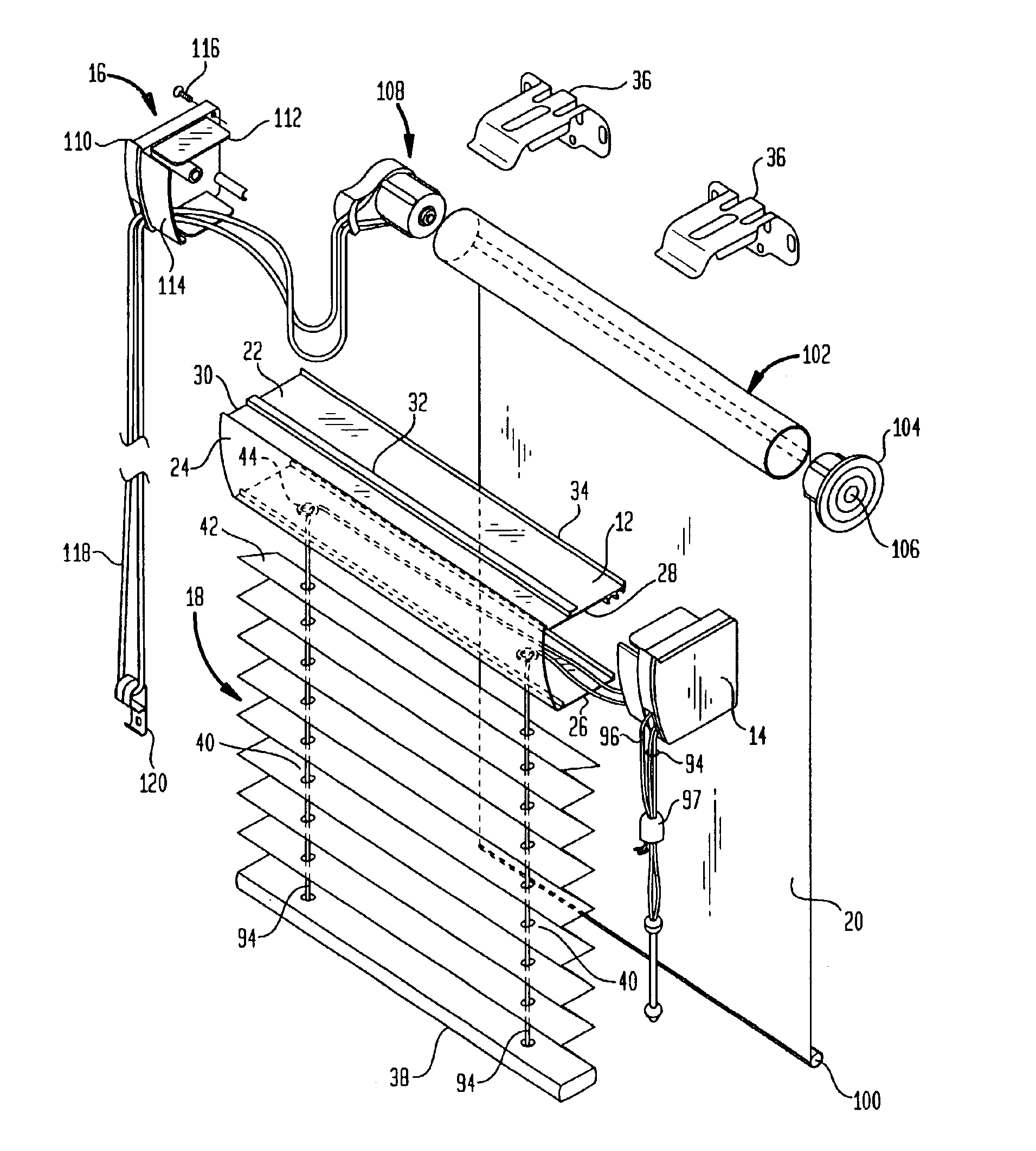
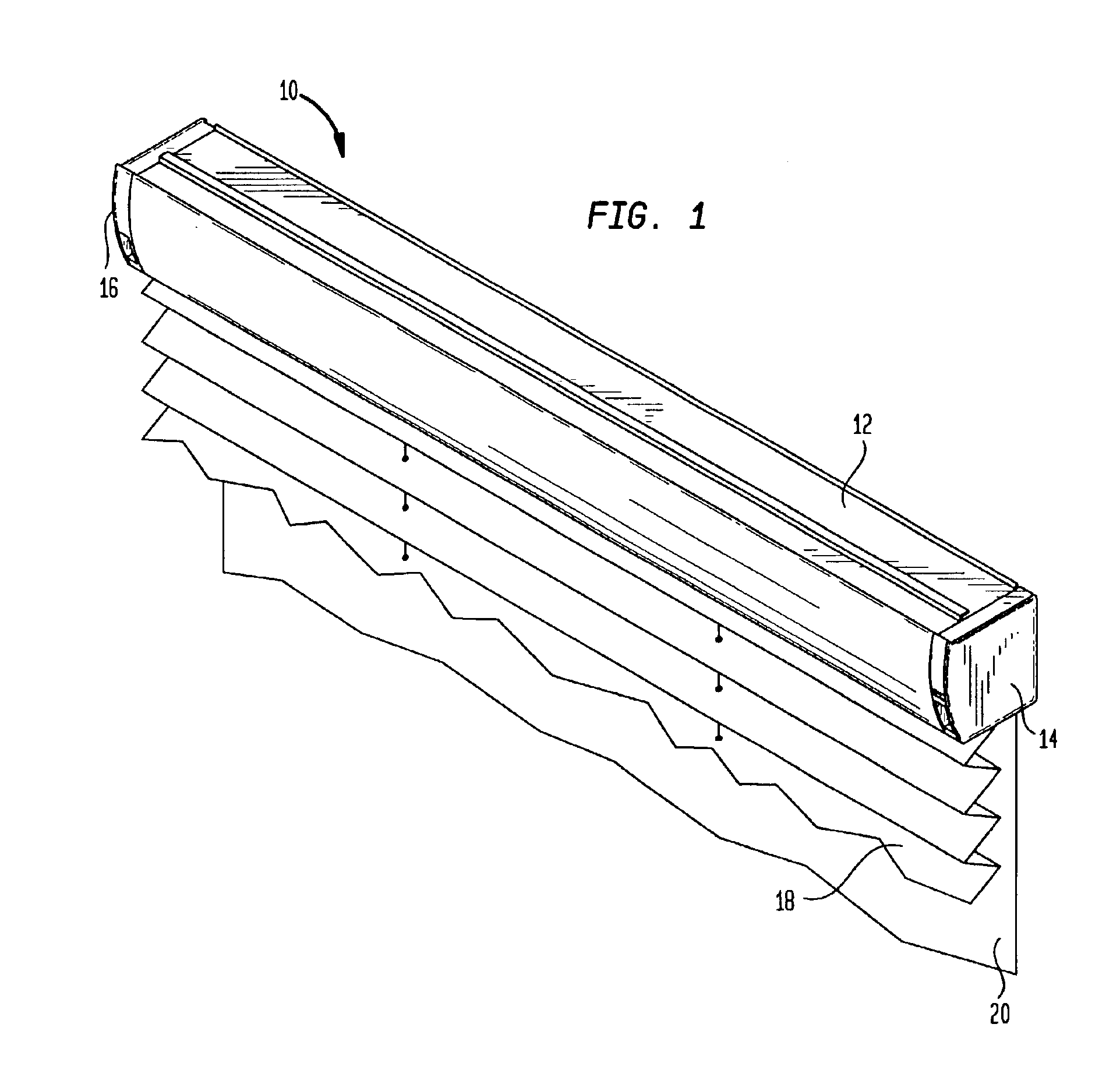
[0022]Turning now to the drawings and particularly to FIGS. 1-3, the double shade of the present invention is shown generally by reference numeral 10. The double shade 10 consists generally of headrail 12, first control module 14, second control module 16, first shade 18 and second shade 20.

[0023]As best shown in FIG. 2, headrail 12 is a generally U-shaped plastic or metal extrusion which extends longitudinally between first control module 14 and second control module 16. The headrail 12 generally includes a top wall 22, a front surface 24, a bottom surface 26, a first side edge 28 and a second side edge 30. The headrail 12 is essentially open at its rear.

[0024]Formed on top surface 12, as part of the same extrusion, are extensions 32 and 34, which are best shown in FIG. 3. Extensions 32 and 34 are designed to engage with mounting brackets 36, which in turn are mounted to a fixed surface in a manner that is well known to those skilled in this art. It is noted at this juncture that b...


PUM


Abstract

A double shade is disclosed as well as a method of assembling same. The double shade includes a headrail, a first shade mounted at its upper end to the bottom surface of the headrail and operable with lift cords, and a first control module mounted at a side edge of the headrail including a cord lock for operating the first shade. A second shade is mounted to a roller positioned within the interior of the headrail. A second control module is mounted at the opposite side edge of the headrail, and includes a clutch that is operable by a cord loop to move the second shade up and down and hold it in a desired location.

Description

FIELD OF THE INVENTION[0001]This invention relates to window coverings and, more particularly, to double shades which include two different shade materials that are mounted parallel to each other which are independently controllable so that the user can raise and lower each of the two shades separately.BACKGROUND OF THE INVENTION[0002]The past several decades have been marked by tremendous growth in the types of window covering materials that are available to purchasers. Starting with roller shades and slatted horizontal blinds, the field of window coverings has blossomed to include a wide array of different types of coverings. These have included pleated shades, Roman shades, cellular shades, and many others.[0003]Among these many choices, there are shade materials which are transparent to some degree, as well as shade materials which are much more opaque, keeping out a much greater degree of light and providing a greater degree of privacy than is offered by shade materials that ar...

Claims


Application Information

Patent Timeline
IPC IPC(8): E06B9/264E06B9/32E06B9/26E06B9/28
CPCE06B9/264E06B9/32
Inventor WARD, ADAMSTRAND, TORALF H.
Owner SPRINGS WINDOW FASHIONS LP
Why Eureka
Try Eureka