
Duplex scanning device

a scanning device and duplex technology, applied in the field of scanning devices, can solve the problems of affecting the smooth scanning of both sides, affecting the smoothness of the scanning process, and the inability to form the entire transportation path in a straight line, so as to achieve the effect of smooth scanning both sides

Inactive Publication Date: 2005-09-13
SEIKO EPSON CORP
View PDF8 Cites 17 Cited by
  • Summary
  • Abstract
  • Description
  • Claims
  • Application Information

AI Technical Summary

Benefits of technology

[0010]The present invention is therefore directed to solving these problems of the prior art, and an object of this invention is to provide a small duplex scanning device capable of smoothly scanning both sides of an original document without paper jams occurring.SUMMARY OF THE INVENTION

Problems solved by technology

However, the entire transportation path cannot be formed in a straight line in scanners having a reversing mechanism, and jams occur easily when transporting thin documents and thick documents.
Furthermore, the curvature of the transportation path tends to cause thick originals to curl.
This curl can also cause the original document to lift away from the sensor surface, and thus tends to degrade scanned image quality.
Furthermore, adding the transportation path needed to reverse the original document necessarily increases the overall size of the product.
A problem with duplex scanners having two scanning sensors is that the duplication of parts results in a more complicated construction and a higher cost.
With the prior art method described above, however, a large space is needed to rotate the image sensor and platen roller because of the large radius of rotation required by the image sensor and platen roller, and this increases the size of the product.
Furthermore, because a straight transportation path cannot be formed with the above-described prior art, paper jams occur easily during transportation, the paper lifts away from the sensor surface, and scanning quality is easily degraded.

Method used


Image

  • Duplex scanning device
  • Duplex scanning device
  • Duplex scanning device

Examples


Embodiment Construction

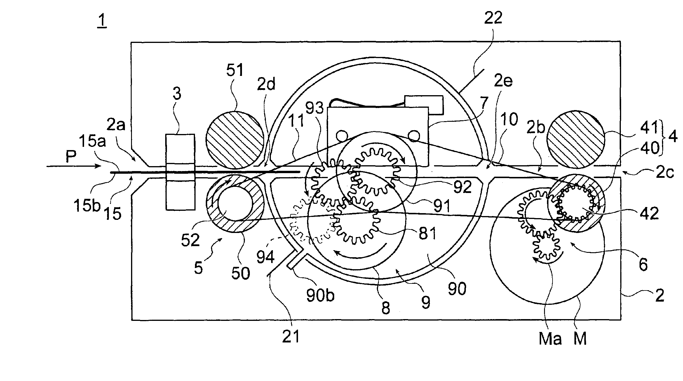
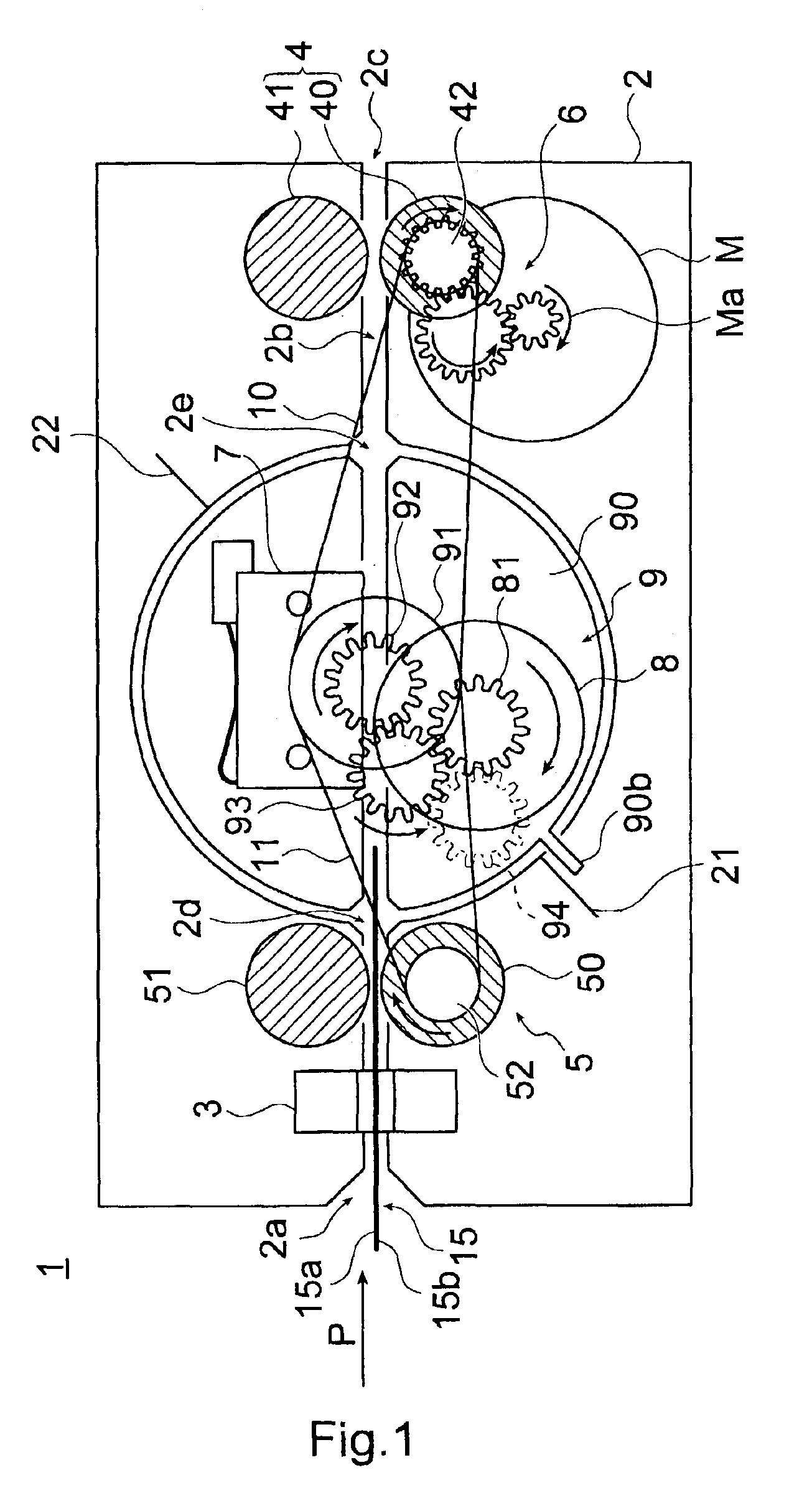
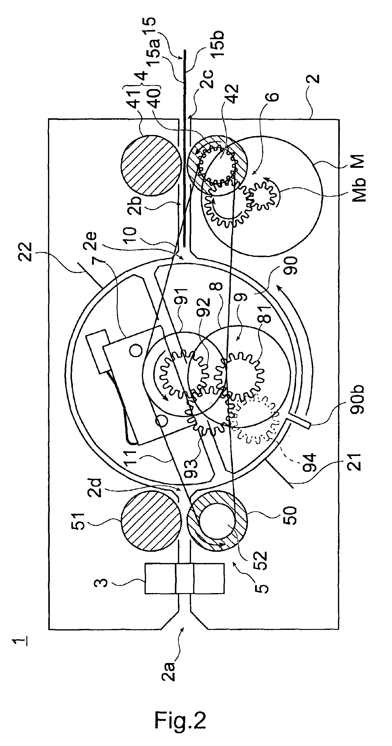
[0028]A preferred embodiment of a scanning device according to the present invention is described below with reference to the accompanying figures.

[0029]FIG. 1 to FIG. 4 illustrate the configuration and operation of a scanning device according to this preferred embodiment of the invention; FIG. 5 and FIG. 6 are perspective views showing major components of the rotation mechanism of the same embodiment; and FIG. 7 and FIG. 8 are perspective views showing the scanner part in the same embodiment.

[0030]As shown in FIG. 1, a scanning device 1 according to this embodiment of the invention has a paper insertion opening 2a for receiving inserted paper (original document) 15 positioned on one end of the box-shaped housing 2 (also referred to as a stationary frame below), and a paper feed path (transportation path) 2b passing straight through the housing 2 from the paper insertion opening 2a to the paper exit 2c at the opposite end of the housing 2. This paper exit 2c enables the paper 15 to ...


PUM


Abstract

A compact duplex scanner for scanning both sides of an original document scans a document smoothly without paper jams. A platen roller 8 is located opposite an image sensor 7 for scanning a paper 15 held therebetween as it is transported through a paper feed path 2b. The image sensor 7 and platen roller 8 are mounted on a rotary frame 90 designed to move circularly as a single unit around a rotary shaft positioned transversely to the paper feed path 2b. After the paper 15 is carried in a forward direction P and the front 15a of the paper 15 is scanned, the rotary frame 90 rotates 180 degrees, and the paper 15 is carried in a reverse direction to scan the back 15b.

Description

BACKGROUND OF THE INVENTION[0001]1. Field of the Invention[0002]The present invention relates to a scanning device used in products such as facsimile machines, scanners, and multi-function printers (MFP), and relates more particularly to a duplex scanning device for scanning both sides of an original document.[0003]2. Description of the Related Art[0004]Duplex scanners according to the prior art for scanning both sides of a document have either had a mechanism for reversing the original document or two sensors for scanning the opposite sides of the document.[0005]However, the entire transportation path cannot be formed in a straight line in scanners having a reversing mechanism, and jams occur easily when transporting thin documents and thick documents. Furthermore, the curvature of the transportation path tends to cause thick originals to curl. This curl can also cause the original document to lift away from the sensor surface, and thus tends to degrade scanned image quality. Furth...

Claims


Application Information

Patent Timeline
IPC IPC(8): H04N1/00H04N1/12H04N1/191H04N1/193
CPCH04N1/00572H04N1/00586H04N1/00588H04N1/00594H04N1/00602H04N1/1215H04N1/193
Inventor ENDO, KATSUYUKIFURIHATA, HIDEKI
Owner SEIKO EPSON CORP
Learn More