Optical apparatus

a technology of optical equipment and lens, applied in the field of optical equipment, can solve the problems of high cost of application of this type of light coating, inability to meet the needs of users, and inability to meet the needs of users, and achieve the effect of reducing the ability of the lens to transmit light from the general field of vision to the eye, and being easy to s

Inactive Publication Date: 2005-09-13
GREENHOUSE INT
View PDF2 Cites 1 Cited by
  • Summary
  • Abstract
  • Description
  • Claims
  • Application Information

AI Technical Summary

Benefits of technology

[0011]In order to generate a satisfactory first image a compromise must be struck between a number of variable factors. The intensity of the second image, which may be referred to as a ghost image, must be substantially less than the intensity of the first or primary image. As is explained hereinafter the relative intensities can be manipulated by judicious choices of the absorption and the refractive index of the lens material. Sufficient light energy must be reflected from the outer reflective surface to create a primary image of acceptable intensity. This image should be preferably viewed against a contrasting background, which is formed by the first lens, so that it is readily visible.
[0014]Preferably the lens material has at least 70% absorption which carries with it the benefit that the second intensity is less than about 9% of the first intensity. The “strength” of the second image is thus significantly reduced.
[0015]Preferably however the lens material has between 80% to 85% absorption. This will ensure a signal (first image) to noise (second image) ratio which is greater than 25:1 ie. the second image has an intensity which is less than 4% of the intensity of the first image. This produces a highly satisfactory contrast between the first and second images.
[0018]The first lens is preferably of substantially uniform thickness. The thickness of the first lens should be as small as is practicable and ideally the lens should be less than 2 mm in thickness. The reason for this is that the second image is moved closer towards the first image as the thickness of the lens is decreased. The effect of the second image may then be such that it results only in a small degree of blurring of the first image without creating a distinct and separate second image.

Problems solved by technology

The application of this type of light coating can be expensive and, if the coating is not of a satisfactory material, the coating can be easily damaged by scratching, abrasion or the like.
To some extent this imbalance is compensated for by an external lens or visor which covers both eyes but the overall appearance of the end product can be unacceptable to certain users.
Also, the different light intensities on the eyes of a user can be disturbing and affect the user's vision and balance.
It is known that semi-transparent lenses can generate ghost or secondary images but the problem associated therewith is not identified in the aforementioned American specification nor addressed.
The position of the secondary lens and its size can be problematic and can present a source of physical danger to a user.

Method used


Image

  • Optical apparatus
  • Optical apparatus
  • Optical apparatus

Examples


Embodiment Construction

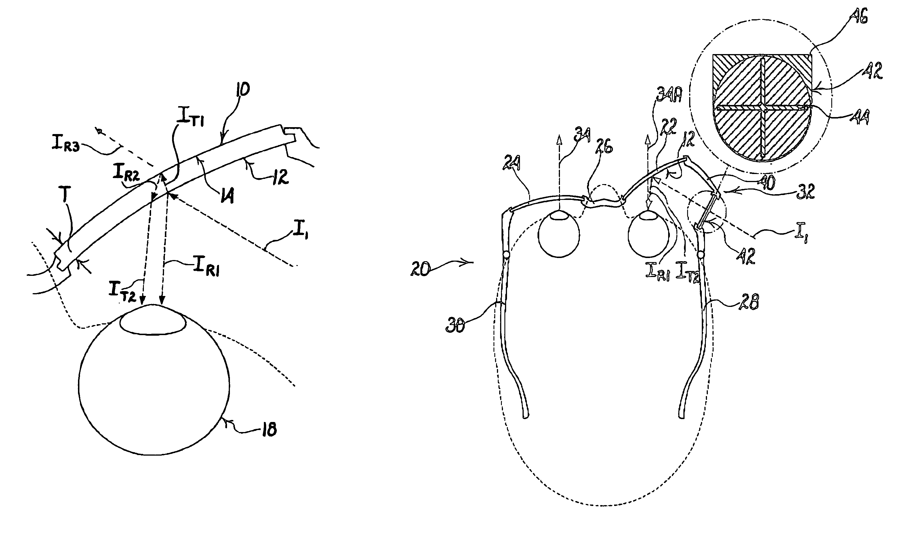
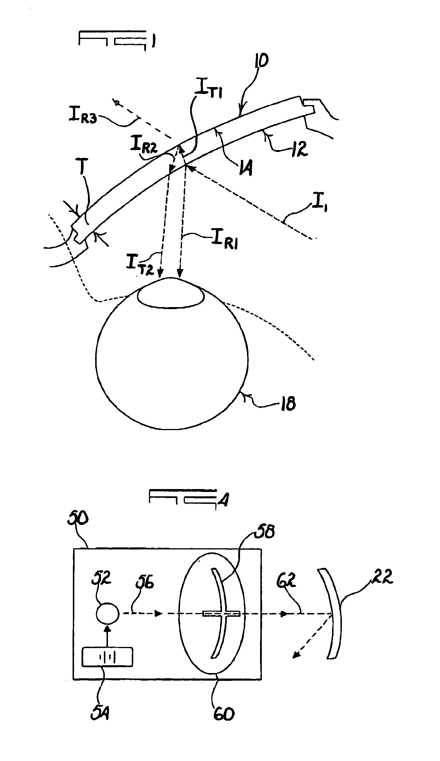
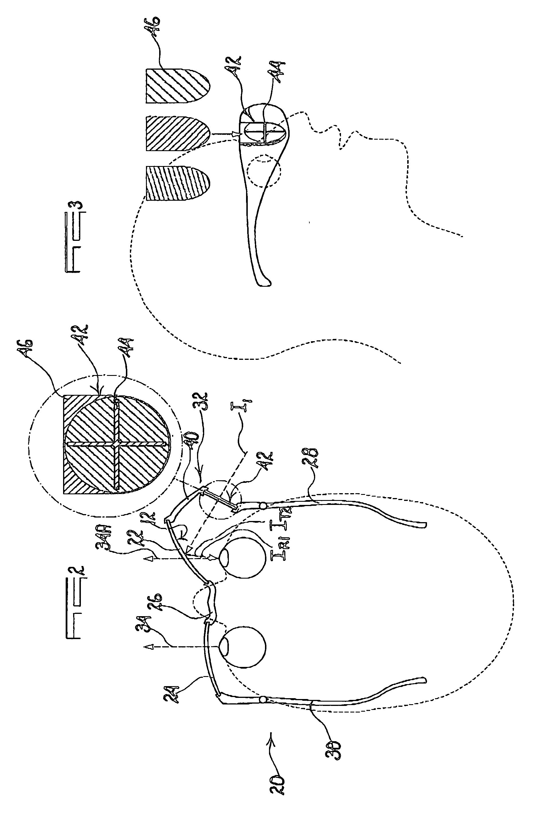
[0029]FIG. 1 of the accompanying drawings illustrates in cross section a lens 10 used in the apparatus of the invention. The lens is made from a light transmissive material eg. glass or a plastic such as polycarbonate, and has an outer reflective surface 12 and an inner reflective surface 14. The lens material has an absorption index A and a reflective index n. The lens is of uniform thickness T, where T is preferably ≦2 mm.

[0030]FIG. 1 illustrates an incident light ray I1 impinging on the outer reflective surface 12. The ray produces a first reflected ray IR1 and a refracted ray IT1. When the latter ray strikes the inner reflective surface 14 a ray IR2 is reflected internally and this is refracted at the interface of the outer surface 12 with atmosphere to produce a ray IT2. At the interface of the inner surface with atmosphere an outgoing refracted ray IR3 is produced.

[0031]A person viewing the rays arising from the outer surface 12 will thus see, with an eye 18, a first, main ima...


PUM


Abstract

An optical apparatus for training a golfer which is the form of a pair of spectacles with tinted lenses, one of which is inclined so that an image projected onto an inner surface of the lens is reflected onto an eye of a user. The image comprises data which aids the golfer in a training stroke. To reduce ghost images, to allow for binocular vision and to superimpose the projected image on a background view, the lenses have an absorption of from 60% to 85%.

Description

BACKGROUND OF THE INVENTION[0001]This invention relates to optical apparatus for creating an image against a background, which is particularly suitable for use as a training aid for a golfer.[0002]It is desirable in various situations to have an image which is superimposed against a background view. For example a golfer, addressing a ball, can be assisted in his stroke if an image, which is visible only to the golfer, is superimposed on his normal field of vision. This type of situation is described for example in the specification of international application No. PCT / IB02 / 00953.[0003]This international application describes a system wherein light is concentrated by a collector element and then passed through a reticle (a light grid) which directs an image onto a reflector which is in the nature of a beam splitter and which reflects light from the reticle towards an eye while at the same passing light in a direction from a normal field of vision. Normally the fabrication of a beam s...

Claims


Application Information

Patent Timeline
Patent Type & Authority Patents(United States)
IPC IPC(8): G02C5/00G02C7/00G02B27/01G02C7/10G02B27/00A63B69/36G02C11/00G02B27/02G02C7/02
CPCA63B69/3608G02B27/0172G02C7/105G02C5/001G02C7/104G02B2027/012G02B2027/019G02B2027/0178A61H23/0218A61H23/006
Inventor VAN STRAATEN, WILLEM JOHANNES
Owner GREENHOUSE INT
Why Eureka
Try Eureka