Rapidly adjustable threaded pin clamp

a threaded pin and clamping technology, applied in the field of clamps, to achieve the effect of quick and accurate positioning of threaded fixation pins

Inactive Publication Date: 2005-09-13
UNIV OF LOUISVILLE RES FOUND INC
View PDF15 Cites 32 Cited by
  • Summary
  • Abstract
  • Description
  • Claims
  • Application Information

AI Technical Summary

Benefits of technology

[0012]The present invention is a clamp for the rapid and accurate positioning of threaded fixation pins used for attaching a frame or immobilizing device to a bone structure. A preferred clamp made in accordance with the present invention has a central body defining a channel therethrough for receiving a fixation pin. In use, the preferred clamp is mounted or otherwise fixed in space relative to the bone into which the fixation pin is to be inserted. The fixation pin is inserted into and pushed forward through the channel defined through the central body of the clamp until the rotary cutting tip of the fixation pin is in contact with the patient.

Problems solved by technology

However, if the forward advance caused by the engagement of the threads of the fixation pin with the locking member can not keep pace with the cutting action, the resultant resistance to insertion in the form of a rearward directed force will cause the locking member to rise up and disengage the threads of the fixation pin, allowing the rotation of the fixation pin to continue without any forward advance.

Method used


Image

  • Rapidly adjustable threaded pin clamp
  • Rapidly adjustable threaded pin clamp
  • Rapidly adjustable threaded pin clamp

Examples


Embodiment Construction

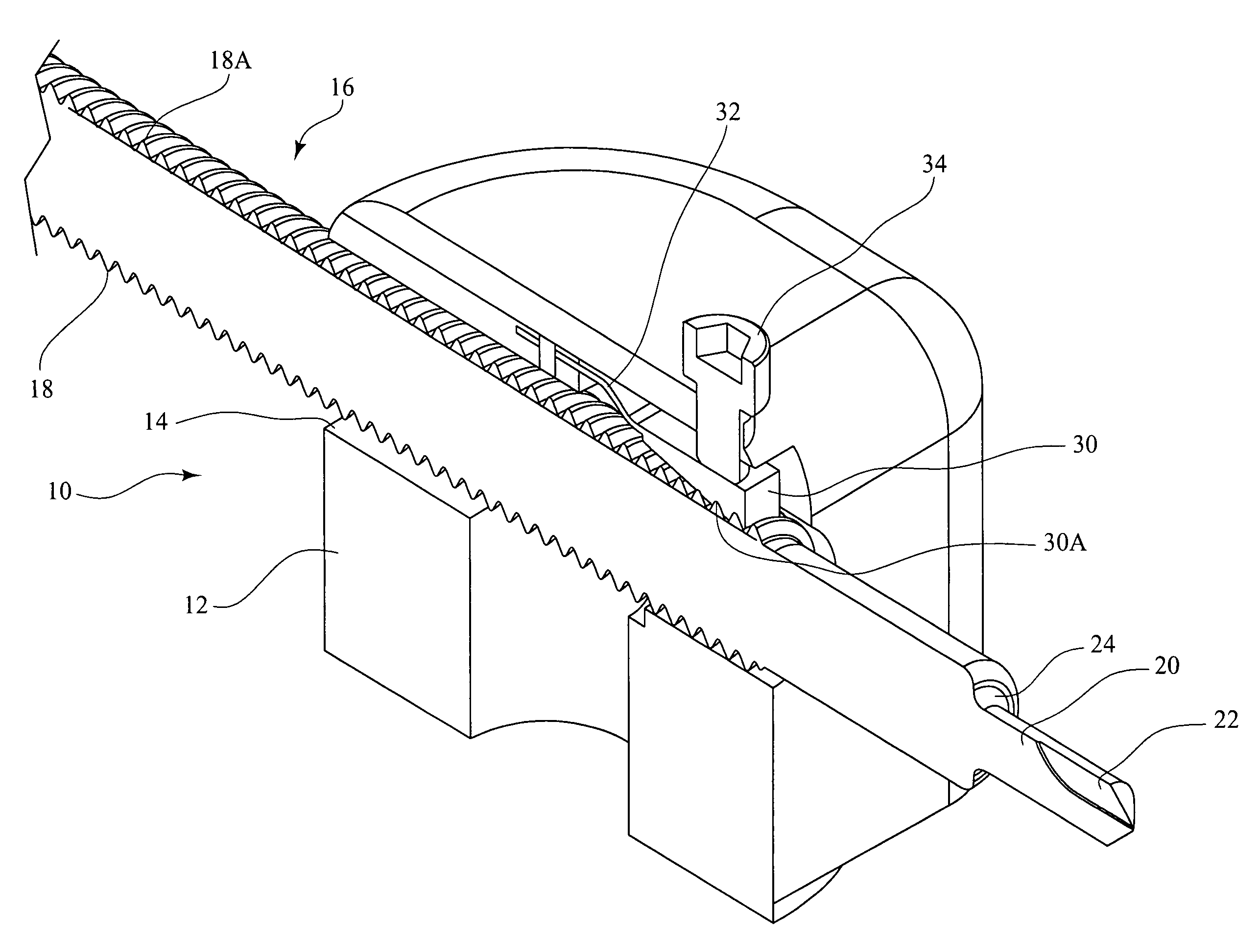
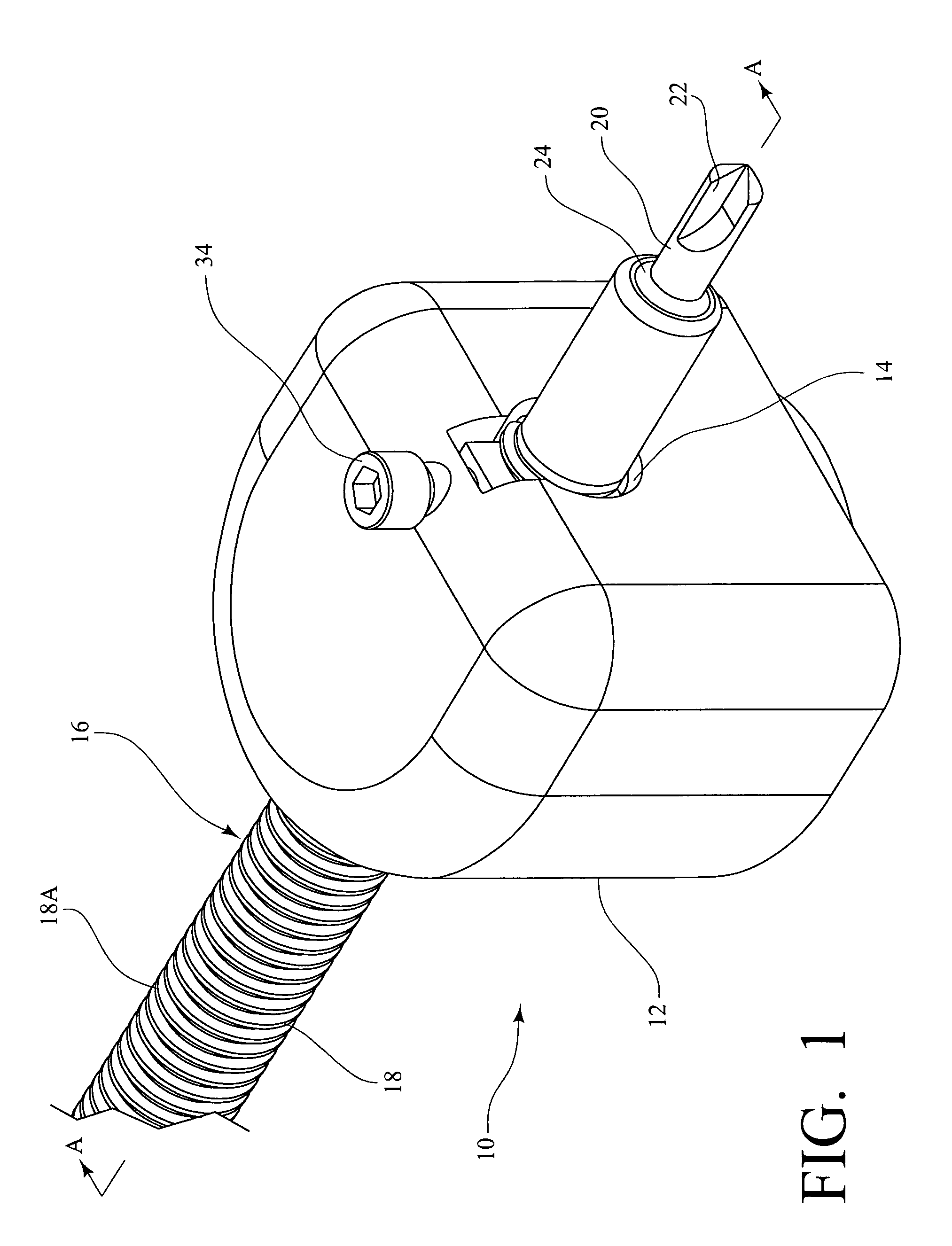
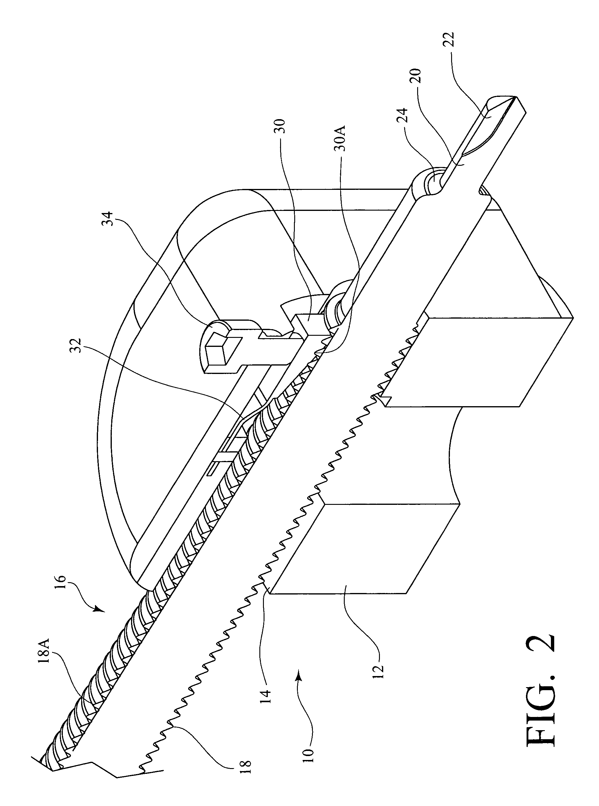
[0021]The present invention is a clamp for the rapid and accurate positioning of threaded fixation pins used for attaching a frame or immobilizing device to a bone structure. FIGS. 1–4 provide various perspective and sectional views of a preferred clamp 10 made in accordance with the present invention.

[0022]As shown in FIGS. 1–4, the preferred clamp 10 has a central body 12 defining a channel therethrough 14 for receiving a fixation pin 16. In this regard, as described in the '210 patent referenced above, the fixation pin 16 preferably comprises a body 18 with threads 18a provided along a portion of its length, a cylindrical post 20 coaxially secured to (and, in this preferred embodiment, integral with) the leading end of the body 18, a rotary cutting tip 22 formed in the face of the post 20, and a radial shoulder 24 formed along the boundary of the body 18 and the post 20. Nevertheless, it is contemplated that other threaded fixation pins could be positioned using the preferred cla...


PUM


Abstract

A clamp for the rapid and accurate positioning of a threaded fixation pin has a central body defining a channel therethrough for receiving a fixation pin. The clamp also includes a locking member with a lower surface adapted to engage and mate with the threads of the fixation pin. Thus, the fixation pin can be rapidly inserted into the desired bone structure by rotating the fixation pin, and as the fixation pin is rotated, it also advances forward due to the engagement of the threads of the fixation pin with the locking member of the clamp. If the forward advance caused by the engagement of the threads of the fixation pin with the locking member can not keep pace with the cutting action, the resultant resistance to insertion in the form of a rearward directed force will cause the locking member to rise up and disengage the threads of the fixation pin.

Description

CROSS-REFERENCE TO RELATED APPLICATIONS[0001]The present application claims priority to U.S. Provisional Application Ser. No. 60 / 384,866 filed May 31, 2002, the entire disclosure of which is incorporated herein by reference.BACKGROUND OF THE INVENTION[0002]The present invention relates to fixation pins for attaching a frame or immobilizing device to a bone structure of a patient with a skeletal injury, and, more particularly to a clamp for the rapid and accurate positioning of such fixation pins.[0003]In cases of skeletal injuries, such as broken bones and cervical spinal injuries, it is often necessary to fix or stabilize the position of the bones while the injury heals. For example, such fixation may require the attachment of an external frame to long bones or the attachment of a halo orthosis to the skull of a patient. To attach such a frame or immobilizing device to a bone structure, fixation pins are commonly used. A common fixation pin comprises a threaded cylindrical body, a ...

Claims


Application Information

Patent Timeline
Patent Type & Authority Patents(United States)
IPC IPC(8): A61B17/56A61B17/64
CPCA61B17/645A61B17/6458
Inventor VOOR, MICHAEL J.WADDELL, SEID W.
Owner UNIV OF LOUISVILLE RES FOUND INC
Why Eureka
Try Eureka