
Wireless network cloud platform system based on lighting nodes

A wireless network and lighting node technology, applied in the field of wireless network cloud platform system, can solve problems such as wiring difficulties, channel preemption, high construction costs, etc., and achieve the effects of saving manpower and material costs, quickly and accurately positioning, and reducing troubleshooting time

Inactive Publication Date: 2013-12-11
HUAQING KESHENG BEIJING INFORMATION TECH CO LTD
View PDF4 Cites 32 Cited by
  • Summary
  • Abstract
  • Description
  • Claims
  • Application Information

AI Technical Summary

Problems solved by technology

These systems have powerful functions and can realize intelligent control of various lighting equipment, but they are large in scale, expensive, and specific in purpose. It is difficult to use wired wiring, high in construction costs, and poor in versatility.
[0004] The wireless networking technology represented by WIFI is not suitable for lighting control in commercial places, industrial places or municipal projects due to its poor penetration, poor security and stability (it is easily attacked by the same type of WIFI equipment and channel preemption).
[0005] In addition, a wireless lighting network system represented by Zigbee Light Link has recently appeared on the market, which can realize small-scale wireless lighting control: control of local and remote lamps, area lighting, timing switches and other functions, but due to the need to Integrate more resources to process the internal mechanism of the protocol stack. Therefore, when there are many network nodes, the internal resource consumption is serious and the processing performance cannot keep up. Therefore, there is a common problem of network capacity, and the actual network scale is limited (less than 50 points). , For brick-concrete structures or reinforced concrete structures, the signal penetration ability is limited, and it is mainly used as an intelligent solution for home lighting

Method used


Image

  • Wireless network cloud platform system based on lighting nodes
  • Wireless network cloud platform system based on lighting nodes

Examples


Embodiment Construction

[0024] Embodiments of the present invention are described in detail below, examples of which are shown in the drawings, wherein the same or similar reference numerals designate the same or similar elements or elements having the same or similar functions throughout. The embodiments described below by referring to the figures are exemplary only for explaining the present invention and should not be construed as limiting the present invention.

[0025] In describing the present invention, it should be understood that the terms "center", "longitudinal", "transverse", "upper", "lower", "front", "rear", "left", "right", " The orientations or positional relationships indicated by "vertical", "horizontal", "top", "bottom", "inner" and "outer" are based on the orientations or positional relationships shown in the drawings, and are only for the convenience of describing the present invention and Simplified descriptions, rather than indicating or implying that the device or element refe...


PUM


Abstract

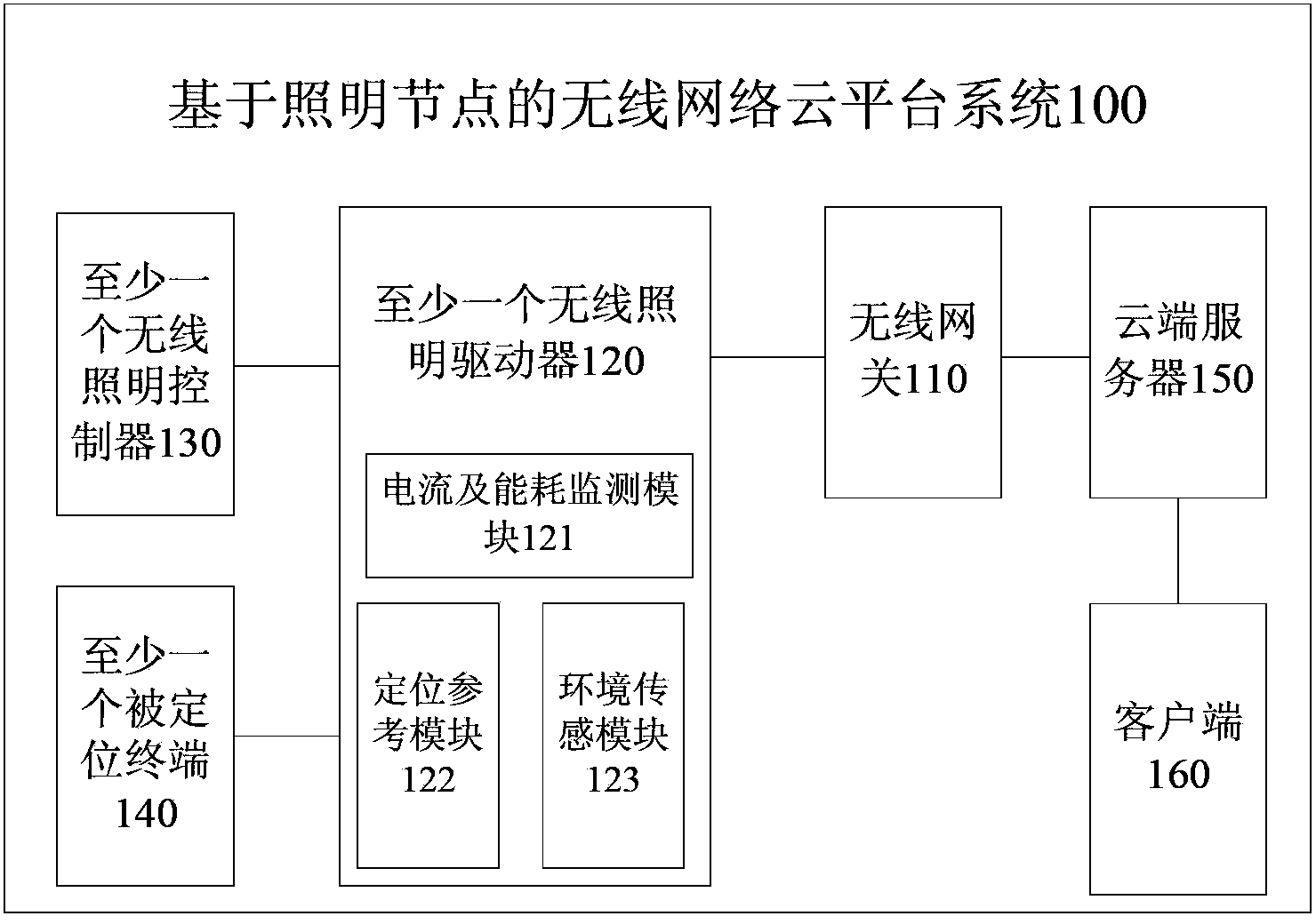
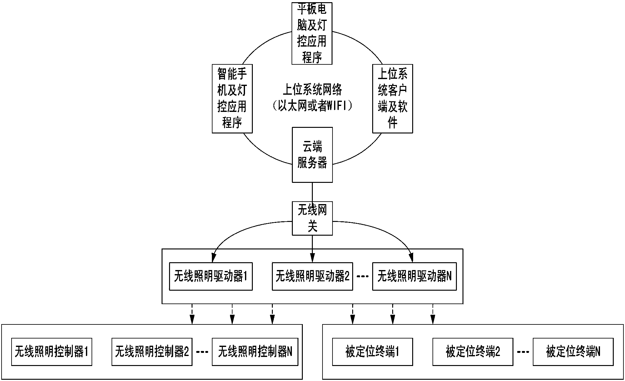
The invention provides a wireless network cloud platform system based on lighting nodes. The wireless network cloud platform system comprises a wireless gateway, at least one wireless lighting driver, at least one wireless lighting controller, at least one positioned terminal and a cloud server client side. A cloud server is connected with a wireless gateway, issues configuration information to the at least one wireless lighting driver and the at least one wireless lighting controller for configuration, controls the at least one wireless lighting driver and judges whether faults exist in a lighting line or not according to a current and energy consumption of the lighting line. Position monitoring is carried out on the positioned terminal according to the positioning information of the positioned terminal, the environment in a preset area is monitored according to environment parameters, and monitoring data are displayed to a user. According to the embodiment, wired lighting control is replaced with the wireless lighting, and labor cost and material cost can be saved. In addition, lighting energy consumption is monitored in real time, dimming is carried out according to current illuminance, and therefore electric energy consumption can be saved.

Description

technical field [0001] The invention relates to the technical field of lighting control, in particular to a lighting node-based wireless network cloud platform system. Background technique [0002] With the continuous development of modern building science and technology and the popularization of information equipment, the intelligentization of control equipment in modern buildings has become the trend of today's building development. However, for a long time, intelligent lighting equipment has been neglected in China, and most buildings still use traditional lighting methods, which are not conducive to centralized monitoring and management, but also have low efficiency in the use of electric energy, wasting a lot of electric energy. [0003] At present, the lighting is monitored by the dedicated bus of building automation, such as RS485 bus, CAN bus, HDL-BUS, CEBUS, LonWorks and so on. These systems have powerful functions and can realize intelligent control of various lig...

Claims


Application Information

Patent Timeline
Patent Type & Authority Applications(China)
IPC IPC(8): H04L29/08H05B37/02
CPCY02B20/40
Inventor 王凡吴杰
Owner HUAQING KESHENG BEIJING INFORMATION TECH CO LTD
Learn More