Transmission shift rail position sensor

a technology of position sensor and shift rail, which is applied in the direction of instruments, galvano-magnetic hall-effect devices, mechanical equipment, etc., can solve the problems of limiting the access to the end of the rail, and the possibility of accurate measuremen

Active Publication Date: 2010-05-27
DEERE & CO
View PDF18 Cites 33 Cited by
  • Summary
  • Abstract
  • Description
  • Claims
  • Application Information

AI Technical Summary

Benefits of technology

[0007]These and other objects are achieved by the present invention, wherein a transmission shift mechanism has shift ranges which are selected by axially moving a shift rail which is slidable in a rail bore in a housing. A shift rail position sensing system includes a groove formed in the shift rail and a Hall effect sensor. The groove has a curved bottom surface, a first flat ramp surface extending from one side of the bottom surface to an outer p

Problems solved by technology

Because the rail must travel through a total distance of approximately 20 mm, it is not possible to accurately sense rail position throughout the entir

Method used


Image

  • Transmission shift rail position sensor
  • Transmission shift rail position sensor
  • Transmission shift rail position sensor

Examples


Embodiment Construction

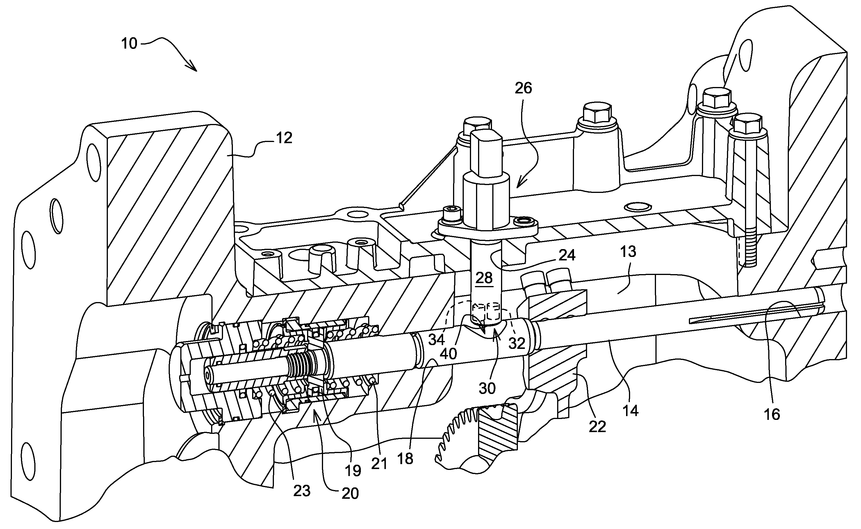
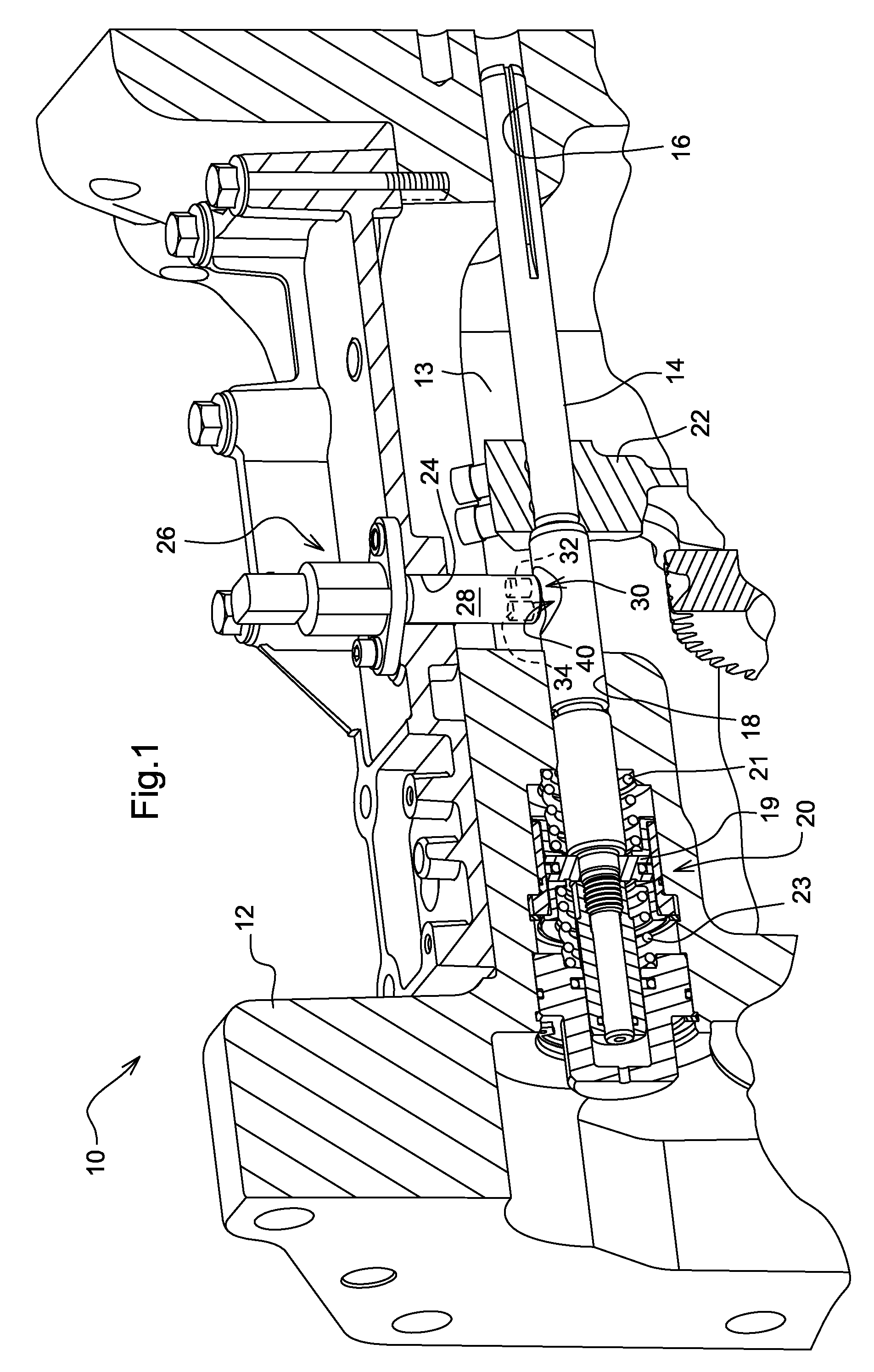
[0011]Referring to FIG. 1, a transmission range shift unit 10 includes a hollow housing 12 which encloses a plurality of range selector or shift rails or rails 14, one of which is shown in FIG. 1. The rail 14 slides over a distance of approximately 20 millimeters (mm) in rail bores 16 and 18 formed in the housing 12. The movement of the rail 14 is controlled by a hydraulic actuator 20. A shift fork 22 is fixed to a central part of the rail 14. The fork 22 operatively engages with transmission gears (not shown). The actuator 20 includes a piston 19 attached to an end of the shift rail 14. Hydraulic pressure will be supplied to either side of the piston 19 to move the shift rail to the desired position. When pressure is not applied to the piston 19, the shift rail 14 is held in a neutral position by springs 21 and 23. The housing forms a chamber 13. The shift fork 22 is attached to the shift rail 14 within the chamber 13.

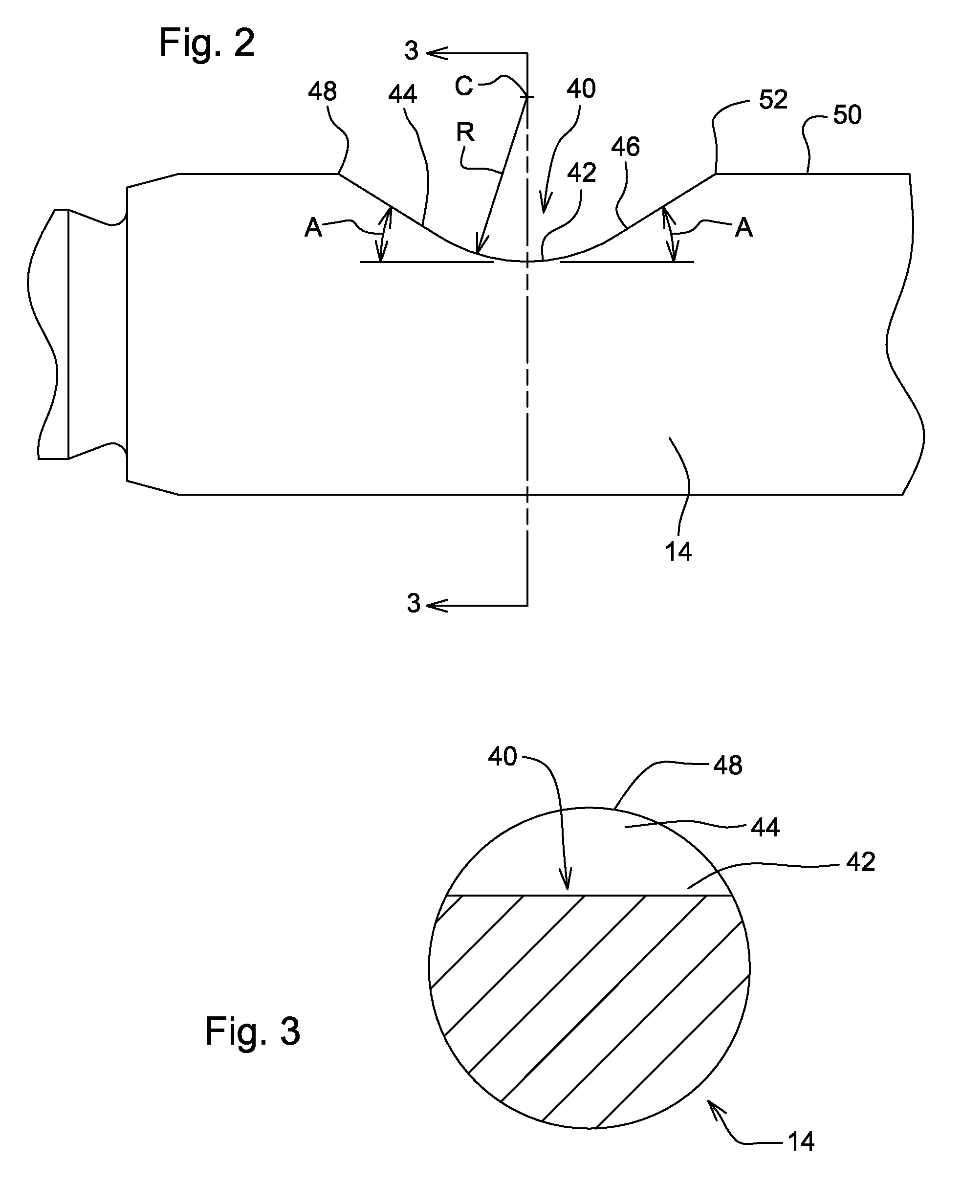
[0012]The housing 12 also forms a sensor bore 24. The sensor bor...


PUM


Abstract

The invention relates to a shift rail position sensing system. There is a need for a rapid and accurate shift rail position sensing system. In a transmission shift mechanism shifts are performed by axially moving a shift rail which is slidable in a rail bore in a housing. A rail position sensing system includes a groove formed in the shift rail and a Hall effect sensor. The groove includes a curved bottom surface, a first ramp surface extending from one side of the bottom surface to an outer peripheral surface of the shift rail, and a second ramp surface extending from a second side of the bottom surface to an outer peripheral surface of the shift rail. The Hall effect sensor has a sensor shaft with an axis normal to an axis of the shift rail. The sensor shaft has a sensing tip which adjacent to and spaced apart from the groove, so that the Hall effect sensor is sensitive an entire range of positions of the shift rail.

Description

FIELD OF THE INVENTION [0001]The present invention relates to a transmission shift rail position sensor.BACKGROUND OF THE INVENTION [0002]Certain large production tractors have transmissions which are shiftable among a plurality of shift or gear ranges. For example, on transmissions used in John Deere 7030 large-frame tractors, range shifts among five ranges are performed with a manually-actuated clutch arrangement.[0003]It is proposed to perform such shifts electronically with a mechanism which includes a range-selection-shaft or shift rail which is translated axially to control the meshing of synchronizers and gears. The synchronizers and gears are fully meshed only within the last 1.0 mm of rail travel. It is therefore necessary to accurately sense the position of a range-selection-rail in order to prevent clutch engagement before the synchronizers are fully engaged with gears (an event which would cause damage to the drivetrain components). Therefore, a sensor is needed to sense...

Claims


Application Information

Patent Timeline
IPC IPC(8): G01B7/00G01R33/00
CPCF16H59/70F16H2063/3079F16H63/30
Inventor WENZEL, GARY HERMANDEFORD, NATHAN PAUL
Owner DEERE & CO
Why Eureka
Try Eureka