Fluorescence Reflection Imaging Device with Two Wavelengths

Inactive Publication Date: 2009-02-12
COMMISSARIAT A LENERGIE ATOMIQUE ET AUX ENERGIES ALTERNATIVES
View PDF8 Cites 32 Cited by
  • Summary
  • Abstract
  • Description
  • Claims
  • Application Information

AI Technical Summary

Benefits of technology

[0010]One object of the invention is to remedy these shortcomings and in particular to enable rapid and

Problems solved by technology

The corresponding equipment is generally bulky.
The methods used generally present problems of shaping of the lighting beam and of autofluorescence.
However, in

Method used


Image

  • Fluorescence Reflection Imaging Device with Two Wavelengths
  • Fluorescence Reflection Imaging Device with Two Wavelengths
  • Fluorescence Reflection Imaging Device with Two Wavelengths

Examples


Embodiment Construction

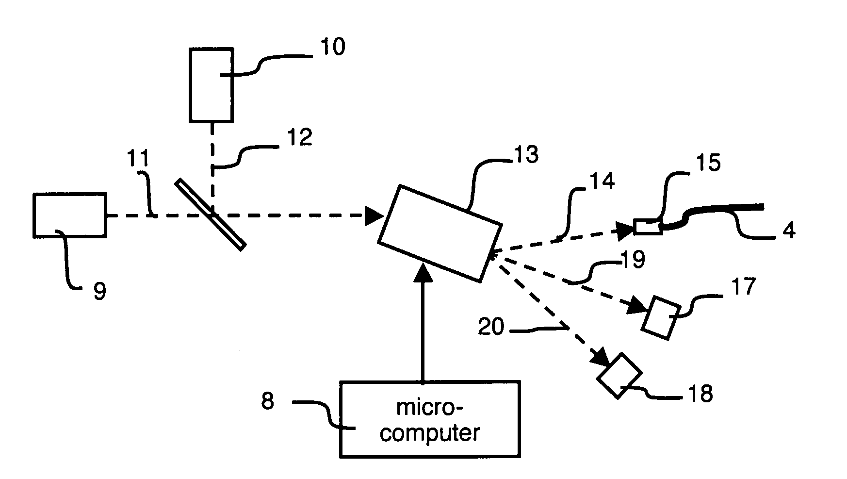
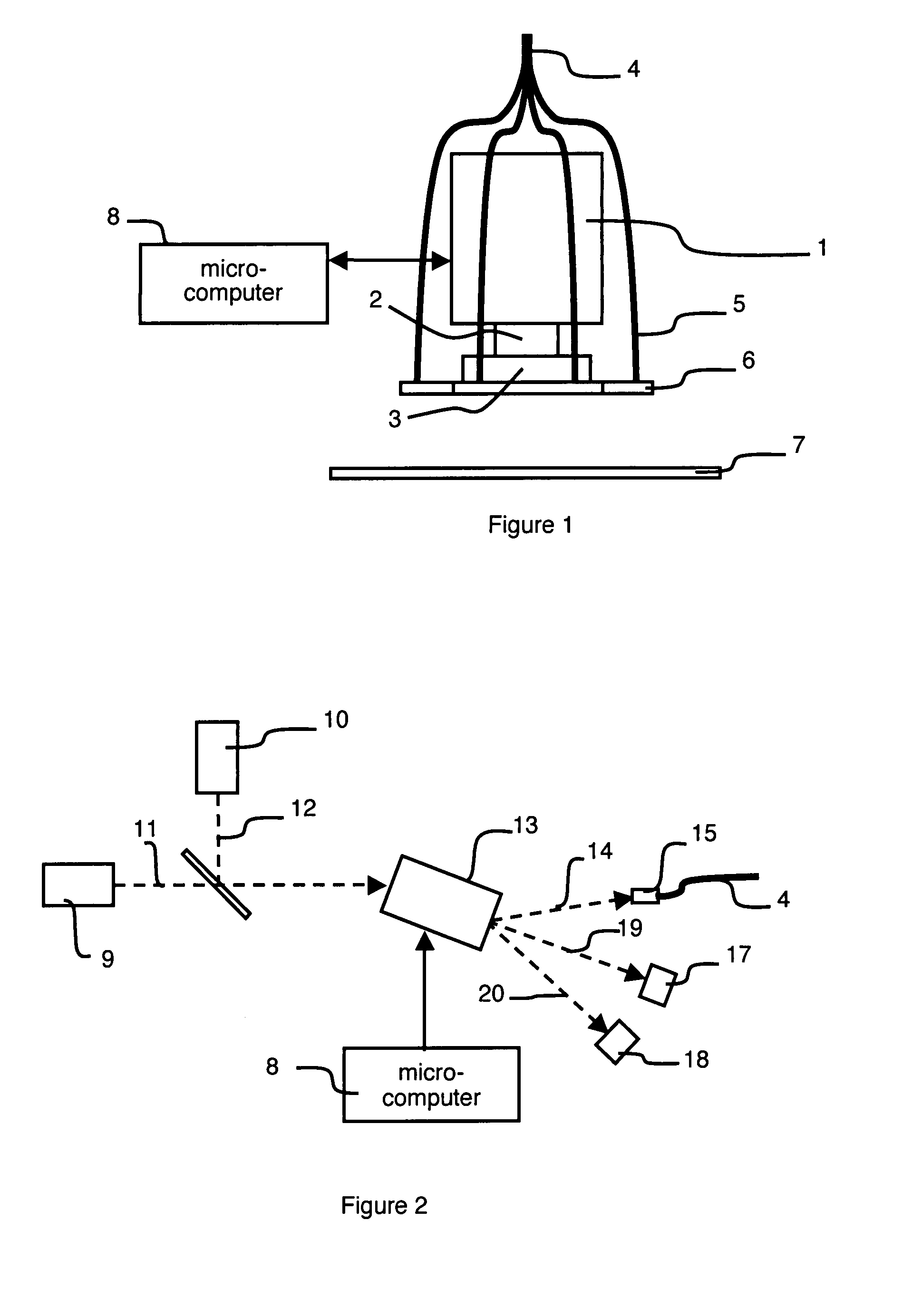
[0017]In FIG. 1, the imaging device comprises a camera 1 equipped with a lens 2 and a filter 3. In the particular embodiment represented in FIG. 2, light is conveyed to the camera 1 by a main optic fiber 4 which is connected to a plurality of optic fibers 5 attached to a ring-shaped light diffuser 6 enabling an object arranged on an object support 7, for example a biological sample, to be uniformly illuminated. The object can also be an operation area. The object is marked by a marking fluorophore. The camera detects the light emitted by the object by means of the filter 3 and transmits signals representative of images to a processing unit, for example a microcomputer 8.

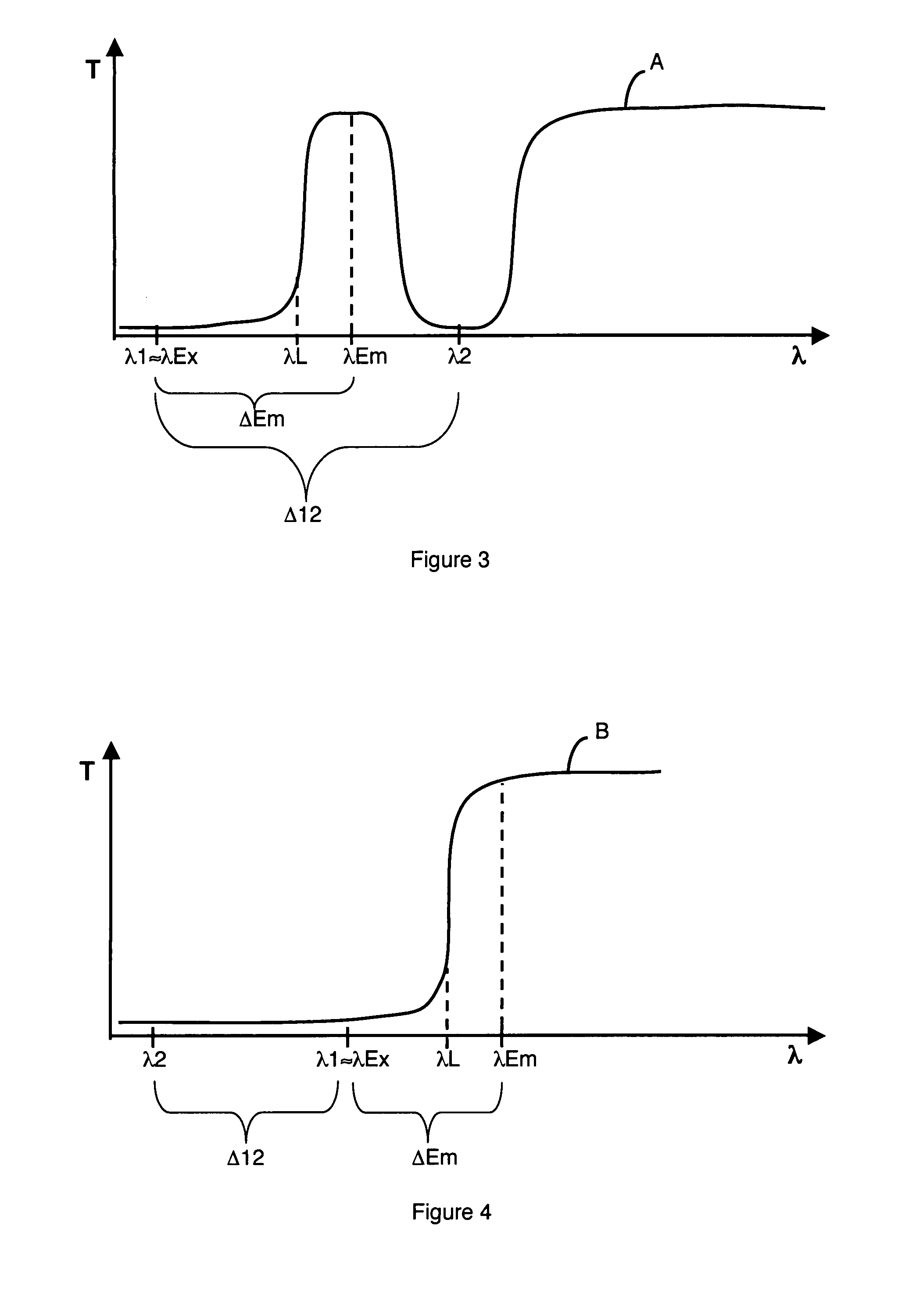
[0018]A first light source 9 and a second light source 10 are represented in FIG. 2. The first light source 9 emits a first light beam 11 having a first wavelength λ1 corresponding substantially to an excitation wavelength λEx of the marking fluorophore. The marking fluorophore presents a main emission wavelength λEm...


PUM


Abstract

A first light source has a first wavelength corresponding to an excitation wavelength of a fluorophore. The excitation wavelength and an emission wavelength of the fluorophore delineate a predetermined interval. A second light source has a second wavelength offset with respect to the first wavelength so as to be outside said predetermined interval. The offset between the first and second wavelengths is comprised between 30 nm and 100 nm. A camera comprises a filter opaque to the first and second wavelengths and transparent to the emission wavelength and to wavelengths substantially higher than the higher of the first and second wavelengths. The light sources and camera are synchronized to alternately activate one of the light sources and make the camera alternately acquire a fluorescence image and a background noise image.

Description

BACKGROUND OF THE INVENTION[0001]The invention relates to a fluorescence reflection imaging device comprising at least a first light source of a first wavelength corresponding substantially to an excitation wavelength of a marking fluorophore presenting a main emission wavelength, the excitation wavelength and the main emission wavelength delineating a predetermined interval, the device comprising a camera and at least a second light source of a second wavelength, offset with respect to the first wavelength, so that the second wavelength is outside said predetermined interval.STATE OF THE ART[0002]Fluorescence Reflection Imaging (FRI) is a widely used technique for in vivo fluorescence. It consists in performing fluorescence imaging of zones marked by a fluorophore more often than not coupled with an antibody which fixes itself specifically on unhealthy tissues or organs, for example cancerous tissues. The FRI technique is also used for in vitro imaging, for example for reading bioc...

Claims


Application Information

Patent Timeline
IPC IPC(8): C12Q1/00G01J3/42G06T7/40
CPCA61B1/0638A61B1/043A61B1/00186G01N21/64A61B1/0655
Inventor PELTIE, PHILIPPEBERGER, MICHELSAUZE, ROLANDBONNET, STEPHANE
Owner COMMISSARIAT A LENERGIE ATOMIQUE ET AUX ENERGIES ALTERNATIVES
Why Eureka
Try Eureka