Foot operated motorcycle clutch

a clutch and foot-operated technology, applied in the direction of mechanical control devices, cycle equipment, instruments, etc., can solve problems such as difficulty in finding the neutral position

Inactive Publication Date: 2005-09-20
HUNTER ROBERT M
View PDF15 Cites 27 Cited by
  • Summary
  • Abstract
  • Description
  • Claims
  • Application Information

AI Technical Summary

Benefits of technology

[0007]The device of the present invention is a foot operated clutch mechanism which may be installed as original equipment or used to

Problems solved by technology

With a motorcycle gear selector, it is difficult to find the neutral position and it is therefore necessary to disengage t

Method used


Image

  • Foot operated motorcycle clutch
  • Foot operated motorcycle clutch
  • Foot operated motorcycle clutch

Examples


Embodiment Construction

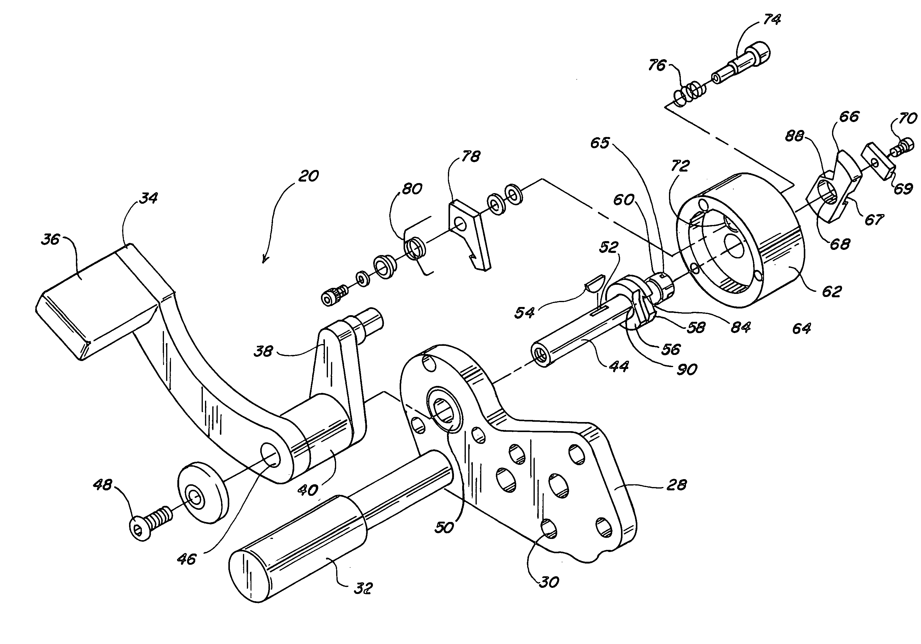
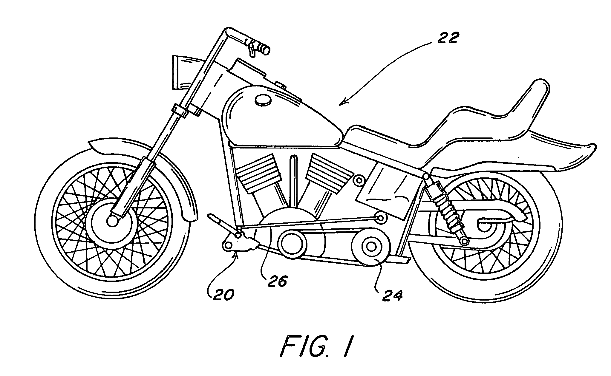
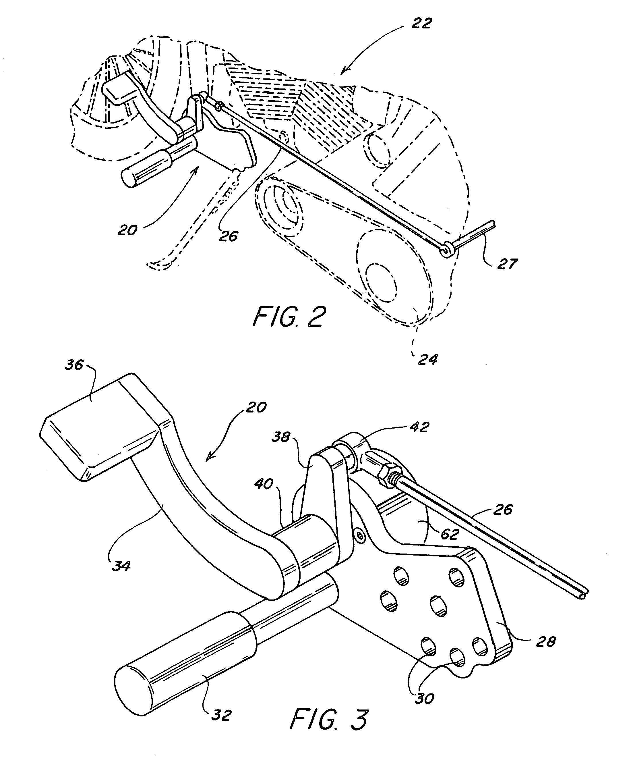
[0025]Referring to FIG. 1, a foot operated clutch mechanism 20 of the invention is shown installed on a conventional modern motorcycle 22. Foot operated clutch mechanism 20 activates a clutch 24 through a clutch activating rod or link 26 and a clutch lever 27. Foot operated clutch mechanism 20 includes a mounting plate 28 which is provided with a plurality of mounting holes 30 which accept mounting bolts to attach the foot operated clutch mechanism to the frame of motorcycle 22, as shown. Mounting plate 28 may also be equipped with a conventional foot rest 32.

[0026]Foot operated clutch mechanism 20 is operated through a foot lever 34 and pedal 36 which drive a rod lever 38 through an intermediate member 40, as best seen in FIG. 3. It will be appreciated that foot lever 34, pedal 36, intermediate member 40 and rod lever 38 are joined to act as a unit without relative movement between these elements. Rod lever 38 drives clutch activating rod 26 through an adjustable tie rod end 42.

[00...


PUM


Abstract

A mechanism to retrofit modern motorcycles with a foot operated clutch or to be installed as original equipment is disclosed. The mechanism has an escapement mechanism, such as a pawl and ratchet, for holding the clutch in disengaged condition when a rider applies positive pressure on a foot pedal without requiring the rider to hold the foot pedal down with his or her left foot. This frees the rider to balance the motorcycle. The mechanism then allows the clutch to be readily reengaged when the rider desires to move the motorcycle by applying further positive pressure to the foot pedal.

Description

BACKGROUND OF THE INVENTION[0001]1. Field of the Invention[0002]The present invention relates to a foot operated clutch for a motorcycle.[0003]2. Brief Description of the Prior Art[0004]Modern motorcycles are typically provided with mechanical clutches in the drive train. The clutches are manually operated by action of a hand lever which drives a cable connected to the clutch. Gear selection is obtained by operation of a foot lever. Older motorcycles, those made in the 1940's and before, were provided with clutches which were foot operated and with hand operated gear selection levers. Such motorcycles include older Harley-Davidson (TM), Moto Guzzi (TM) and Indian (TM) motorcycles, among others.[0005]Recently, there has been a growing nostalgic attraction for older motorcycles. However, there is an insufficient number of such machines available to satisfy the demand for them. In addition, because of short supply, older and collectable motorcycles are very expensive. Consequently, it ...

Claims


Application Information

Patent Timeline
IPC IPC(8): F16D23/00F16D23/12B62K23/08G05G1/30G05G5/06
CPCB62K23/08F16D23/12G05G5/06G05G1/30Y10T74/20648
Inventor HUNTER, ROBERT M.
Owner HUNTER ROBERT M
Why Eureka
Try Eureka