
Electrical connector for circuit board and electrical connector assembly having the same and transmission board

Inactive Publication Date: 2005-09-20
HIROSE ELECTRIC GROUP
View PDF6 Cites 9 Cited by
  • Summary
  • Abstract
  • Description
  • Claims
  • Application Information

AI Technical Summary

Benefits of technology

[0008]Accordingly, it is an object of this invention to provide an electrical connector for a circuit board capable of preventing the transmission of stress caused by external force to a connection section thereof, being easily soldered without soldering defective, and improving electrical characteristics.

Problems solved by technology

In this structure, even if the fixing member receives an external force after the connector is connected to the circuit board, since the bottle neck has large resistance against the transmission of stress, only limited stress is transmitted to the connection member.

Method used


Image

  • Electrical connector for circuit board and electrical connector assembly having the same and transmission board
  • Electrical connector for circuit board and electrical connector assembly having the same and transmission board
  • Electrical connector for circuit board and electrical connector assembly having the same and transmission board

Examples


Embodiment Construction

[0040]Embodiments of the present invention will now be described with reference to the accompanying drawings.

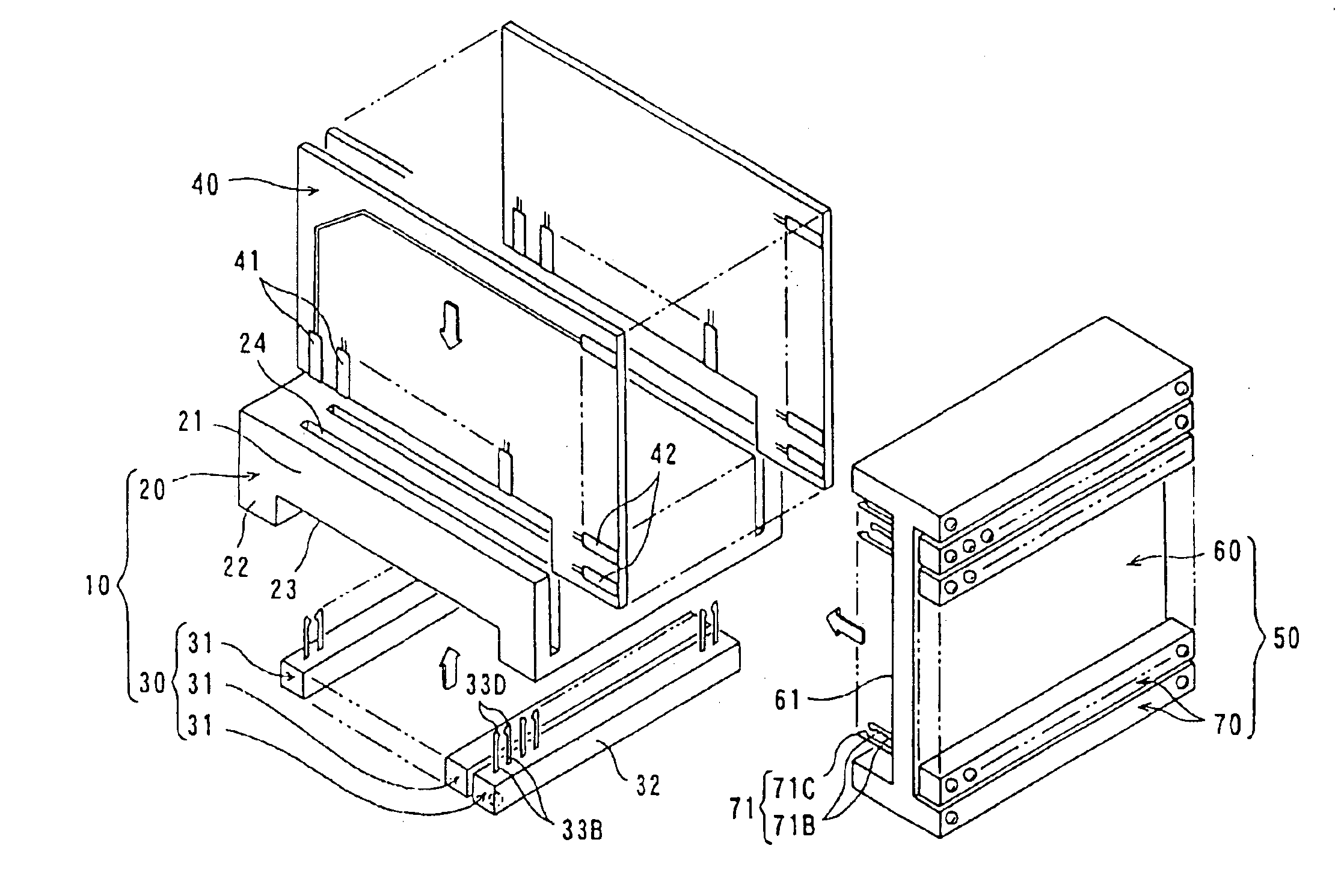
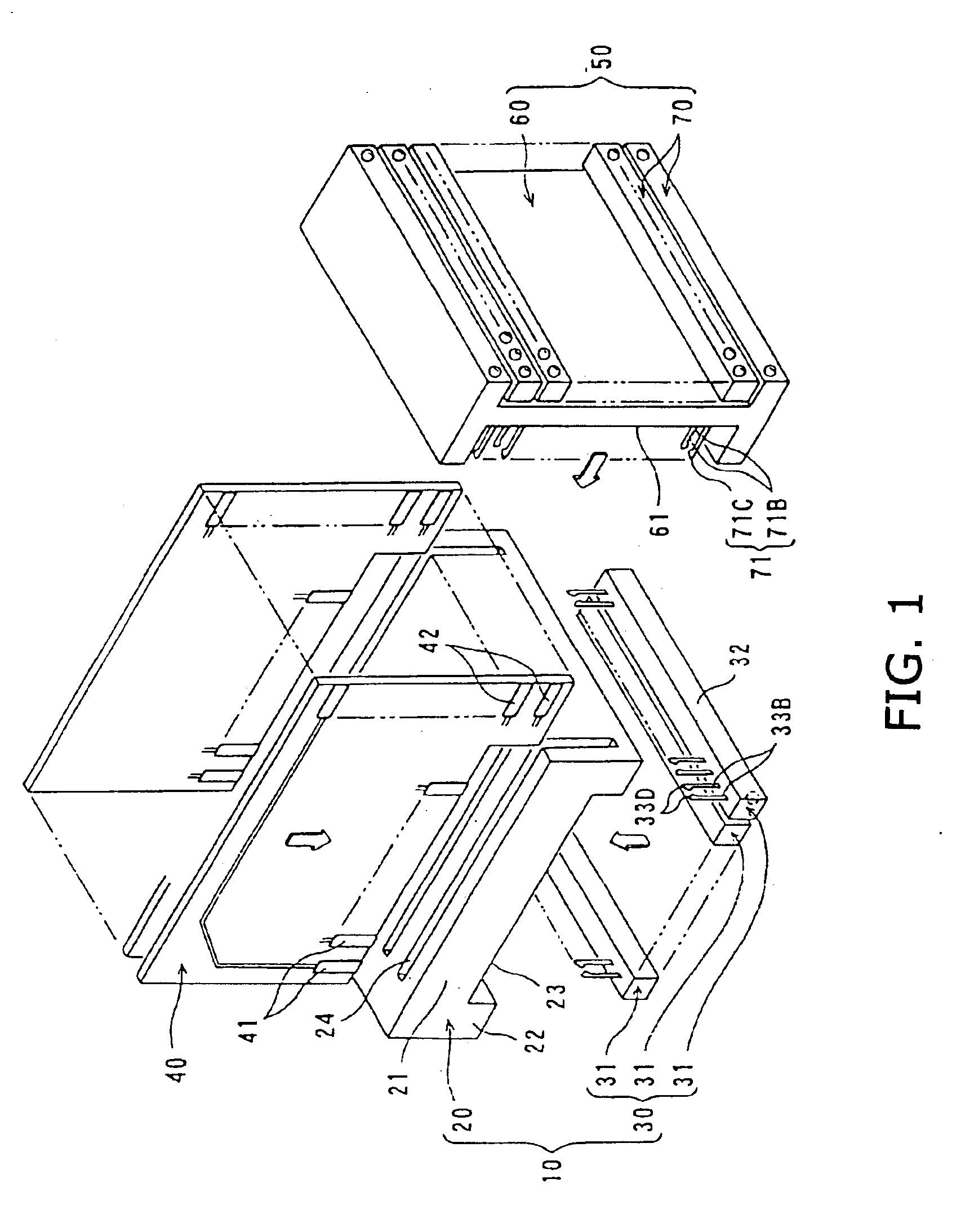
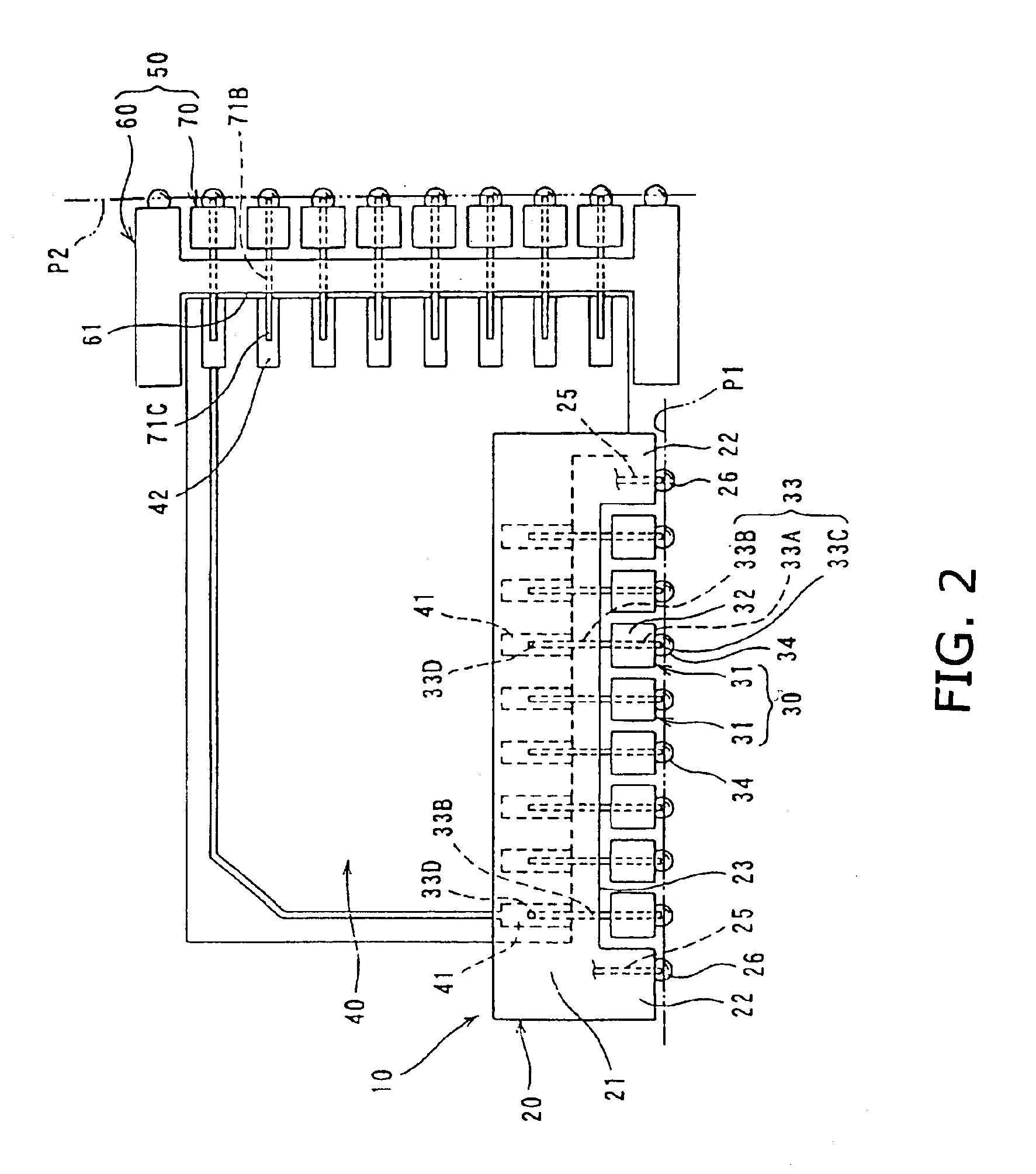
[0041]In FIGS. 1 and 2, a connector 10, which is mounted on a circuit board P1, comprises a fixing member 20 and a plurality of connection members 30. A plurality of transmission boards 40 are connected to the connector 10 and another connector 50 is connected to the transmission boards 40. FIGS. 1 and 2 show conditions before and after the respective members are assembled for connection, respectively.

[0042]The fixing member 20 of the connector 10 has a first housing 21 which is made of an electrically insulating material. The first housing 21 is provided with a hollow 23 between legs 22 provided at lower sides thereof and a plurality of accommodation slits 24 provided in parallel and opened to an upper side and one of lateral sides thereof. The accommodation slits 24 extend downwardly up to the hollow 23. Fixing pieces 25, which are fine pieces or pins made by stamping a met...


PUM


Abstract

An electrical connector (10) for a circuit board (P1) includes a fixing member (20) having a first housing (21) with a mount face facing to the circuit board and at least one fixing piece (25) for fixing the first housing to the circuit board, and a connection member (30) having a second housing (32) with a mount face facing to the circuit board and a plurality of terminals (33) connected with circuit traces of the circuit board. The connection member is supported by the fixing member by a bottle neck such that the second housing is spaced from the first housing.

Description

BACKGROUND OF THE INVENTION[0001]1. Field of the Invention[0002]This invention relates to an electrical connector for a circuit board and a connector assembly including the electrical connector, a transmission board connected to the electrical connector, and another connector connected to the transmission board.[0003]2. Description of the Related Art[0004]A conventional electrical connector for a circuit board disclosed in Japanese Patent Application Kokai Number 2001-160436 comprises pin-type terminals which are provided in a housing and have first connection sections in a cavity of the housing and second connection sections projecting from the lower side of the housing for soldering by solder balls.[0005]The conventional connector is disposed at a corresponding position of the circuit board and fixed by a supporter provided in the housing and the second connection sections of the terminals are connected to corresponding circuit trances by melting the soldering balls by application...

Claims


Application Information

Patent Timeline
IPC IPC(8): H01R13/631H01R13/514H01R13/639
CPCH01R12/712H01R13/6315
Inventor MATSUO, TSUTOMU
Owner HIROSE ELECTRIC GROUP
Learn More