Electrical card connector assembly

Inactive Publication Date: 2008-12-11
HON HAI PRECISION IND CO LTD
View PDF2 Cites 2 Cited by
  • Summary
  • Abstract
  • Description
  • Claims
  • Application Information

AI Technical Summary

Benefits of technology

[0006]Accordingly, the object of the present invention is to provide an el

Problems solved by technology

However, sometimes, the electrical card connector is soldered to the c

Method used


Image

  • Electrical card connector assembly
  • Electrical card connector assembly
  • Electrical card connector assembly

Examples


Example

[0013]Reference will now be made to the drawing figures to describe the present invention in detail.

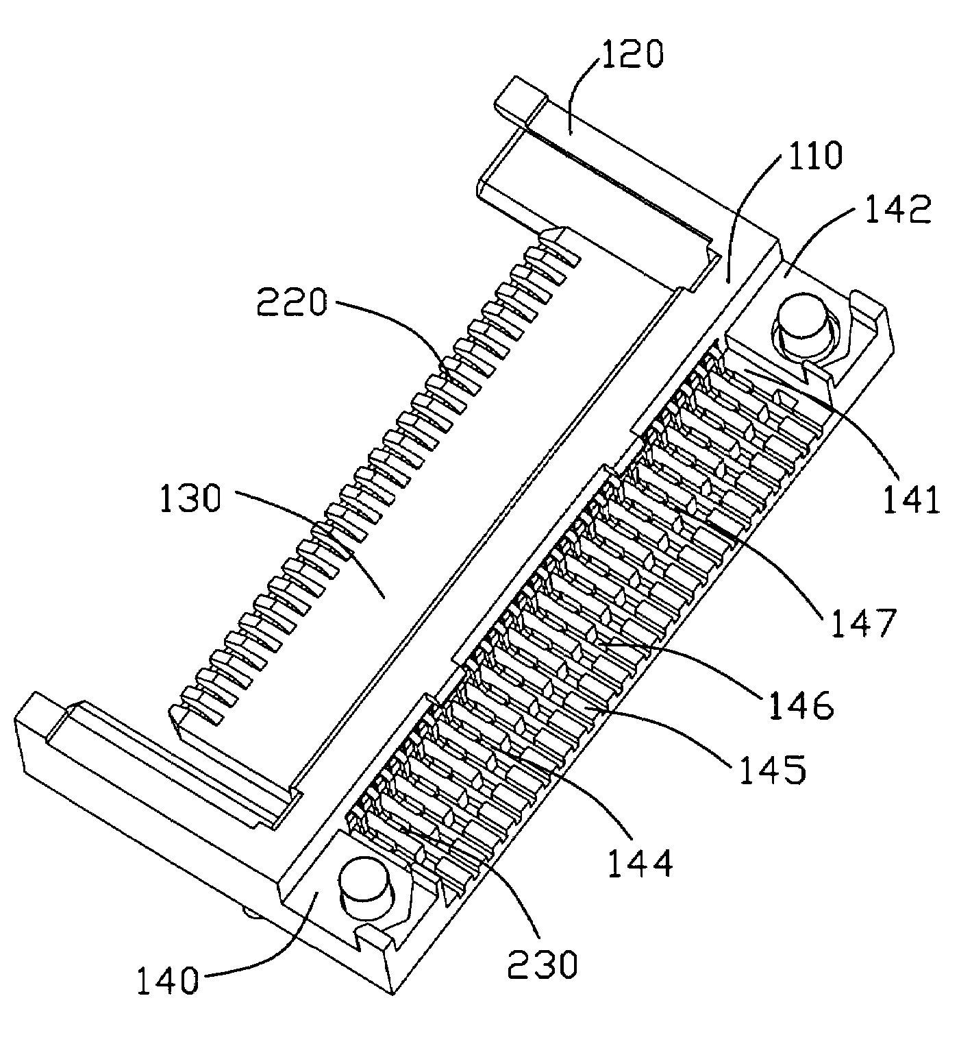
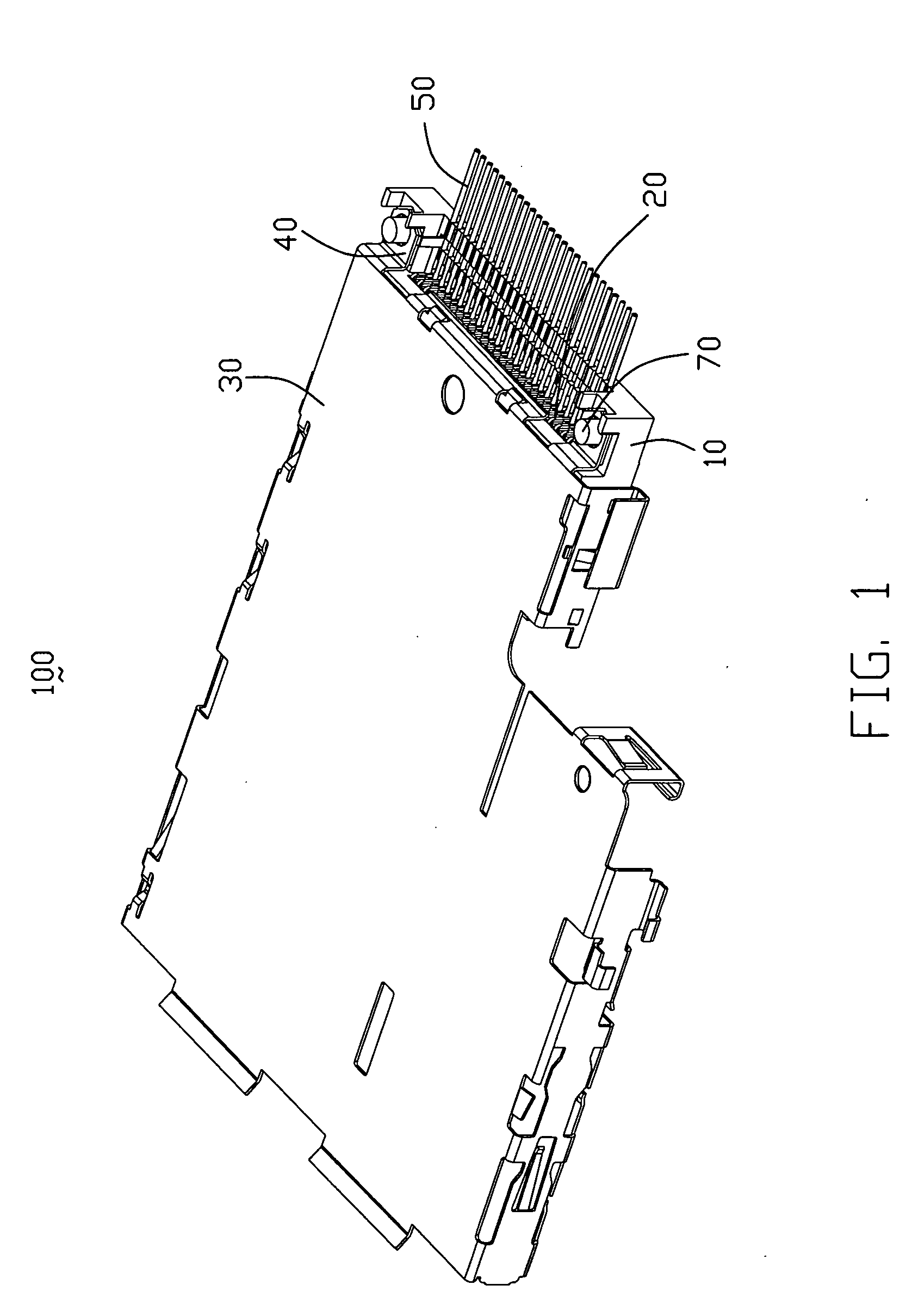
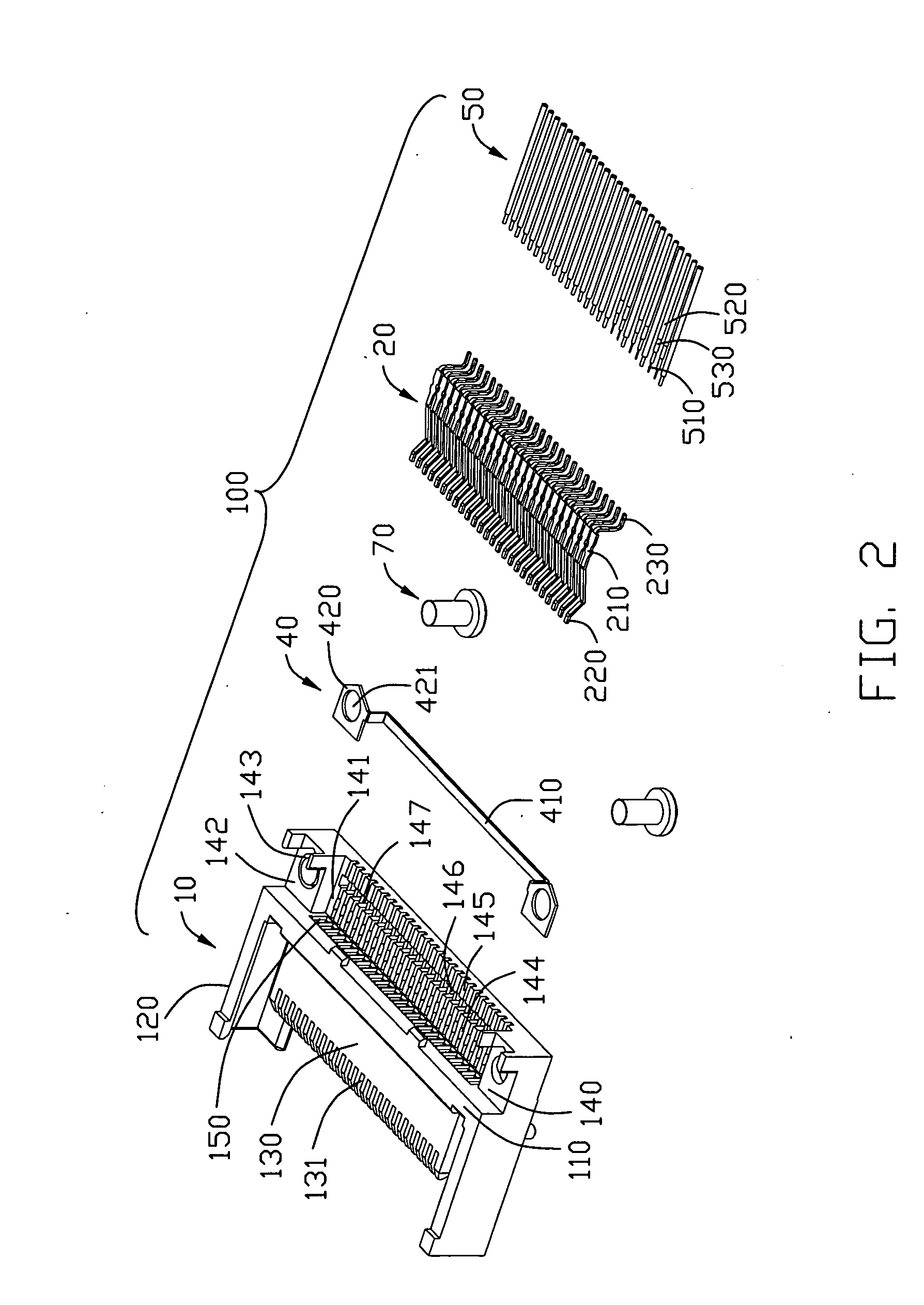
[0014]Referring to FIG. 1 to FIG. 4, an electrical connector assembly 100 comprises an insulating housing 10, an L-shape cover 30 assembled on the insulating housing 10, a plurality of terminals 20 received in the insulating housing 10, a grounding plate 40 mounted on the insulating housing 10, and a plurality of cables 50 soldered with the terminals 20 and partially retained on the insulating housing 10.

[0015]The insulating housing 10 comprises a longitudinal main body 110, a pair of arms 120 extending from the opposite ends of the main body 110, a tongue portion 130 extending from the main body 110 and sandwiched by the arms 120, and a positioning portion 140 extending from the main body 110 opposite to the tongue portion 130. The main body 110 defines a plurality of terminal receiving channels 150, the tongue portion 130 defines a plurality of opening 131 communicating with corresp...


PUM


Abstract

An electrical card connector assembly (100) comprises an insulating housing (10), a plurality of terminals (20) received in the insulating housing, and a plurality of cables (50). The insulating housing comprises a main body (110), a pair of arms (120) extending from the opposite ends of the main body, a tongue portion (130) extending from the main body and sandwiched by the arms, and a positioning portion (140) extending from the main body opposite to the tongue portion, the positioning portion alternatively defines a plurality of channels (145). Each terminal comprises a tail portion (230) received in corresponding channel of the positioning portion. Each cable comprises a conductor located in corresponding channel of the positioning portion and electrically connecting with the tail portion of the terminal.

Description

BACKGROUND OF THE INVENTION[0001]1. Field of the Invention[0002]The present invention generally relates to an electrical card connector assembly, and more particularly to an electrical card connector assembly having a positioning member.[0003]2. Description of Prior Art[0004]Modern times, the PC card is always used as an external equipment for increase the storage of the electrical consumer products, like Mobile phone, Digital camera, etc. The electrical card connector is used for electrically connecting the PC card and the electrical consumer products. Usually, the electrical card connector is mounted on a printed circuit board. However, sometimes, the electrical card connector is soldered to the cables, accordingly, how to located the cables is a new problem for us.[0005]Hence, it is desirable to have an improved card connector to overcome the above-mentioned disadvantages of the prior art.BRIEF SUMMARY OF THE INVENTION[0006]Accordingly, the object of the present invention is to p...

Claims


Application Information

Patent Timeline
IPC IPC(8): H01R25/00
CPCH01R12/592H01R12/721
Inventor LIN, KUO-LUNG
Owner HON HAI PRECISION IND CO LTD
Why Eureka
Try Eureka